Having discovered the article Digital Capacitance Meter on the Internet, I wanted to build this meter. However, the AT90S2313 microcontroller and LED indicators with a common anode were not at hand. But there were ATMEGA16 in a DIP package and a four-digit seven-segment liquid crystal display. The microcontroller pins were just enough to connect it directly to the LCD. Thus, the meter was simplified to just one microcircuit (in fact, there is a second one - a voltage stabilizer), one transistor, a diode, a handful of resistor-capacitors, three connectors and a button. The device turned out to be compact and easy to use. Now I have no questions about how to measure the capacitance of a capacitor. This is especially important for SMD capacitors with capacities of several picofarads (and even fractions of a picofarad), which I always check before soldering them into any board. There are now many desktop and portable meters available, the manufacturers of which claim a lower capacitance measurement limit of 0.1 pF and sufficient accuracy for measuring such small capacitances. However, in many of them, measurements are carried out at a fairly low frequency (a few kilohertz). The question is, is it possible to obtain acceptable measurement accuracy under such conditions (even if a larger capacitor is connected in parallel with what is being measured)? In addition, on the Internet you can find quite a lot of clones of the RLC meter circuit on a microcontroller and an operational amplifier (the same one with an electromagnetic relay and a one- or two-line LCD). However, it is not possible to measure small containers “humanly” with such devices. Unlike many others, this meter is specifically designed for measuring small capacitance values.
As for measuring small inductances (nanogenry units), for this I successfully use the RigExpert AA-230 analyzer, which our company produces.
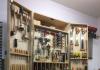
Capacitance meter photo:
Capacitance meter parameters
Measuring range: 1 pF to approximately 470 µF.
Measurement limits: automatic switching of limits – 0...56 nF (lower limit) and 56 nF...470 µF (upper limit).
Indication: three significant figures (two figures for capacitances smaller than 10 pF).
Control: single button for zeroing and calibration.
Calibration: one-time, using two reference capacitors, 100 pF and 100 nF.
Most of the microcontroller pins are connected to the LCD. Some of them also have a connector for in-circuit programming of the microcontroller (ByteBlaster). Four pins are used in the capacitance measurement circuit, including the comparator inputs AIN0 and AIN1, the measurement limits control output (using a transistor) and the threshold voltage selection output. A button is connected to the only remaining pin of the microcontroller.
The +5 V voltage stabilizer is assembled according to a traditional circuit.
The indicator is seven-segment, 4 characters, with direct connection of segments (i.e., non-multiplex). Unfortunately, there were no markings on the LCD. Indicators from many companies, for example, AND and Varitronix, have the same pinout and dimensions (51×23 mm).
The diagram is shown below (the diagram does not show the diode for protection against “polarity reversal”; it is recommended to connect the power connector through it):
Microcontroller program
Since ATMEGA16 is from the “MEGA” series and not from the “tiny” series, there is little point in writing an assembler program. In the C language it is possible to make it much faster and simpler, and a decent amount of flash memory on the microcontroller allows you to use the built-in library of floating point functions when calculating capacity.
The microcontroller performs capacitance measurement in two steps. First of all, the charging time of the capacitor through a resistor with a resistance of 3.3 MOhm (lower limit) is determined. If the required voltage is not reached within 0.15 seconds (corresponding to a capacitance of about 56 pF), the capacitor is charged again through a 3.3 kOhm resistor (upper measurement limit).
In this case, the microcontroller first discharges the capacitor through a 100 Ohm resistor, and then charges it to a voltage of 0.17 V. Only after this the charging time to a voltage of 2.5 V (half the supply voltage) is measured. After this, the measurement cycle is repeated.
When outputting the result, a voltage of alternating polarity (relative to its common wire) with a frequency of about 78 Hz is applied to the LCD terminals. A sufficiently high frequency completely eliminates flickering of the indicator.
.Capacitors are very widely used in all types of electronic circuits and almost no radio circuit can do without them. In this project, we will discuss the technique of building a digital capacitance meter using a PIC microcontroller. This project can measure capacitance values from 1 nF to 99 uF (accordingly, it also measures picofarads). The microcontroller used in this project is PIC16F628A.
The circuit consists of two parts, the first part of the circuit is presented below:
Second part:

The outputs of the second part from the circuit are connected to the outputs of the microcontroller, according to the designations on them.
This capacitance meter is based on the principle of charging a capacitor through a series resistor. If we know the time it takes for the capacitor to charge up to a known voltage, then we can solve this equation for C knowing the value of R.
Knowing the resistor value (in this case it is 22K) and the charging time, we can now solve the capacitor equation to calculate the capacitance C. This is the principle used in the program. The measurement starts when the measurement button is pressed. The measured capacitance is displayed on the LCD display. To power the circuit, a 5V power supply is required.
The microcontroller firmware is written in C. Pro for the PIC compiler. The maximum value of measurable capacitance is 99.99 uF. The program displays the message “Out of Range” if the measured value is out of range. It is clear that microfarads will take longer to measure than pico or nanofarads. The device is quite accurate and the error is only 1 nF.
Note: High-voltage capacitors must be discharged with a high-resistance resistor before starting measurements.
Examples of measured capacities:
 /c]
/c]
With this capacitance meter you can easily measure any capacitance from units of pF to hundreds of microfarads. There are several methods for measuring capacitance. This project uses the integration method.
The main advantage of using this method is that the measurement is based on time measurement, which can be done quite accurately on an MC. This method is very suitable for a homemade capacitance meter, and it can also be easily implemented on a microcontroller.
Working principle of a capacitance meter
Phenomena that occur when the state of a circuit changes are called transient processes. This is one of the fundamental concepts of digital circuits. When the switch in Figure 1 is open, the capacitor is charged through resistor R, and the voltage across it will change as shown in Figure 1b. The relationship determining the voltage on the capacitor has the form:![]()
 Values are expressed in SI units, t seconds, R ohms, C farads. The time during which the voltage on the capacitor reaches the value V C1 is approximately expressed by the following formula:

From this formula it follows that time t1 is proportional to the capacitance of the capacitor. Therefore, the capacitance can be calculated from the charging time of the capacitor.
Scheme
To measure the charging time, a comparator and a microcontroller timer and a digital logic chip are sufficient. It is quite reasonable to use the AT90S2313 microcontroller (the modern analogue is ATtiny2313). The output of the comparator is used as a flip-flop T C1. The threshold voltage is set by a resistor divider. Charging time does not depend on supply voltage. The charging time is determined by formula 2, therefore it does not depend on the supply voltage because the ratio in the formula VC 1 /E is determined only by the divisor coefficient. Of course, during measurement the supply voltage must be constant.Formula 2 expresses the time it takes to charge the capacitor from 0 volts. However, it is difficult to work with voltage close to zero due to the following reasons:
- The voltage does not drop to 0 volts. It takes time for the capacitor to completely discharge. This will lead to increased measurement times.
- Time required between startscharging and starting the timer. This will cause measurement error. For AVR this is not critical because this requires only one clock cycle.
- Leakage current at the analog input. According to the AVR datasheet, current leakage increases when the input voltage is close to zero volts.
To prevent these difficulties, two threshold voltages VC 1 (0.17 Vcc) and VC 2 (0.5 Vcc) were used. The PCB surface must be clean to minimize leakage currents. The required supply voltage for the microcontroller is provided by a DC-DC converter powered by a 1.5VAA battery. Instead of a DC-DC converter, it is advisable to use 9 Vbattery and converter 78 L05, preferablyAlsodo not turn offBOD, otherwise problems may arise with EEPROM.
Calibration
 |
 |
 |
To calibrate the lower range: Using the SW1 button. Next, connect pin #1 and pin #3 on P1, insert a 1nF capacitor and press SW1.
To calibrate the high range: Close pin #4 and #6 of connector P1, insert a 100nF capacitor and press SW1.
The inscription "E4" when turned on means that the calibration value was not found in the EEPROM.
Usage
Automatic ranging
Charging starts through a 3.3M resistor. If the voltage on the capacitor does not reach 0.5 Vcc in less than 130 mS (>57nF), the capacitor is discharged and recharged, but through a 3.3 kOhm resistor. If the voltage on the capacitor does not reach 0.5 Vcc in 1 second (>440µF), the inscription “E2”. When time is measured, the capacity is calculated and displayed. The last segment displays the measuring range (pF, nF, µF).
Clamp
You can use part of a socket as a clamp. When measuring small capacitances (units of picofarads), the use of long wires is undesirable.
On a microcontroller, but after some discussions with fellow radio amateurs and a series of experiments, thoughts came to mind about its further improvement. The new device has increased accuracy and a wider range. It is based on the PIC16F90 controller.
Capacitance and inductance meter circuit
Characteristics of LCR meter
Capacitors:
- 1pF to 1nF - resolution: 0.1 PF, accuracy: 1%
- from 1nF to 100nF - resolution: 1pF, accuracy: 1%
- from 100nF to 1uF - resolution 1nF, error: 2.5%
Electrolytes:
- from 100 NF to 100,000uF - 1nF resolution, accuracy: 5%
Inductance:
- from 10nH to 20H - resolution 10nH, accuracy: 5%
Resistance:
- 1 mOhm to 0.5 Ohm - 1 mOhm resolution, accuracy: 5%

Here you need to get better - the device works more like a milliohmmeter. It almost does not measure resistors larger than one ohm. The printed circuit board for the instrument is designed in such a way that an LCD display can be connected on the top. To adjust the display contrast, use trimming resistor R10.

All resistors are metal film, 1%. Two 1nF capacitors also with a deviation of 1%. The capacitance CX1 - 33nF, is also critical - it must be polypropylene with a high operating voltage of the capacitor (several hundred volts). The throttle should be low Rdc. The meter has a connector for a separate network adapter, which bypasses the power button.

If the device works with an external power adapter, you can increase the brightness of the screen backlight by decreasing the value of resistor R11. Consult your display documentation to select the correct resistor value.

Keep in mind that electrolytic capacitors must be discharged before measurement, otherwise there is a danger of burning the controller. All files for assembling the circuit (several firmware options, printed circuit boards) are in the archive. .
I once found an article on the Internet by an Asian developer, which described a capacitance meter device. It was assembled using a microcontroller and a bunch of “extra” parts. Since the formulas and principle for calculating capacity were given, I decided to make my own device with the minimum required number of elements that will satisfy my needs. Since there was free memory left, I decided to add a frequency meter function.

The device has only two buttons, a reset button (set to “0”) and a button for switching operating modes:
"Frequency meter", "pF measurement", "nF measurement"
The operating principle of the device is based on measuring the time it takes to charge a capacitor to a certain “threshold” voltage. The calculation is made in the microcontroller using the formula below:
where T is the charging time, R is the resistance of the charging circuit, C is the capacitance of the capacitor, VC1 is the voltage on the capacitor at moment T, E is the EMF of the circuit.
The capacitance meter operates in two measurement ranges: “pF-gradation 1pF” and “nF-gradation 1nF”.
Measurement range of the first mode...........................1 pF - 20 nF, accuracy 1 pF
Measuring range of the second mode...........................1 nF - 22 µF, accuracy 1 nF
Measurement range of the third mode.........................1 µF - 2000 µF, accuracy 1 µF
Frequency measurement range...................................10 Hz(*1Hz) - 8 MHz, accuracy 10Hz(*1Hz)
* - For the version of the device with an indicator on the HD44780 controller

DESIGN:
The fuse bits of the microcontroller can be programmed to be clocked from an internal RC oscillator at a frequency of 8 MHz, or clocked from an external quartz resonator.
For those who are having problems finding a suitable display, I am posting the connection diagram and firmware for the character display with the KS0066U (HD4478) driver.
Display TIC 8148...Analogue TIC55M