After working for about a year, my LED Headlight XM-L T6 headlamp began to turn on every once in a while, or even turn off without a command. Soon it stopped turning on completely.
The first thing I thought was that the battery in the battery compartment was failing.
To illuminate the rear LED HEADLIGHT indicator, a regular red SMD LED is used. Marked on the board as LED. It illuminates a plate of white plastic.

Since the battery compartment is located on the back of the head, this indicator is clearly visible at night.

Obviously it won’t hurt when cycling and walking along road routes.

Through a 100 Ohm resistor, the positive terminal of the red SMD LED is connected to the drain of the FDS9435A MOSFET transistor. Thus, when the flashlight is turned on, voltage is supplied to both the main Cree XM-L T6 XLamp LED and the low-power red SMD LED.
We've sorted out the main details. Now I'll tell you what's broken.
When you pressed the flashlight's power button, you could see that the red SMD LED began to shine, but very dimly. The operation of the LED corresponded to the standard operating modes of the flashlight (maximum brightness, low brightness and strobe). It became clear that the control chip U1 (FM2819) is most likely working.
Since it responds normally to pressing a button, then perhaps the problem lies in the load itself - a powerful white LED. Having unsoldered the wires going to the Cree XM-L T6 LED and connected it to a homemade power supply, I was convinced that it was working.
During measurements, it turned out that in maximum brightness mode, the drain of the FDS9435A transistor is only 1.2V. Naturally, this voltage was not enough to power the powerful Cree XM-L T6 LED, but it was enough for the red SMD LED to make its crystal glow dimly.
It became clear that the FDS9435A transistor, which is used in the circuit as an electronic key, is faulty.
I didn’t choose anything to replace the transistor, but bought an original P-channel PowerTrench MOSFET FDS9435A from Fairchild. Here is his appearance.
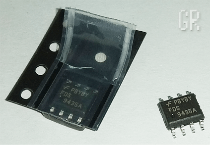
As you can see, this transistor has full markings and the distinctive sign of the Fairchild company ( F ), which released this transistor.
Having compared the original transistor with the one installed on the board, the thought crept into my head that a fake or less powerful transistor was installed in the flashlight. Perhaps even marriage. Still, the lantern did not even last a year, and the power element had already “thrown its hooves away.”
The pinout of the FDS9435A transistor is as follows.

As you can see, there is only one transistor inside the SO-8 case. Pins 5, 6, 7, 8 are combined and are the drain pin ( D rain). Pins 1, 2, 3 are also connected together and are the source ( S ource). The 4th pin is the gate ( G ate). It is to this that the signal comes from the control chip FM2819 (U1).
As a replacement for the FDS9435A transistor, you can use APM9435, AO9435, SI9435. These are all analogues.

You can desolder the transistor using either conventional methods or more exotic ones, for example, using Rose alloy. You can also use the brute force method - cut the leads with a knife, dismantle the case, and then unsolder the remaining leads on the board.
After replacing the FDS9435A transistor, the headlamp began to work properly.

This concludes the story about the renovation. But if I weren’t a curious radio mechanic, I would have left everything as it is. It works fine. But some moments haunted me.
Since initially I did not know that the microcircuit marked 819L (24) is FM2819, armed with an oscilloscope, I decided to see what signal the microcircuit supplies to the transistor gate under different operating modes. It's interesting.
When the first mode is turned on, -3.4...3.8V is supplied to the gate of the FDS9435A transistor from the FM2819 chip, which practically corresponds to the voltage on the battery (3.75...3.8V). Naturally, a negative voltage is applied to the gate of the transistor, since it is P-channel.
In this case, the transistor opens completely and the voltage on the Cree XM-L T6 LED reaches 3.4...3.5V.
In the minimum glow mode (1/4 brightness), about 0.97V comes to the FDS9435A transistor from the U1 chip. This is if you take measurements with a regular multimeter without any bells and whistles.
In fact, in this mode, a PWM (pulse width modulation) signal arrives at the transistor. Having connected the oscilloscope probes between the “+” power supply and the gate terminal of the FDS9435A transistor, I saw this picture.
Picture of a PWM signal on the oscilloscope screen (time/division - 0.5; V/division - 0.5). Sweep time is mS (milliseconds).

Since a negative voltage is applied to the gate, the “picture” on the oscilloscope screen is flipped. That is, now the photo in the center of the screen shows not an impulse, but a pause between them!
The pause itself lasts about 2.25 milliseconds (mS) (4.5 divisions of 0.5 mS). At this moment the transistor is closed.
Then the transistor opens for 0.75 mS. At the same time, voltage is supplied to the XM-L T6 LED. The amplitude of each pulse is 3V. And, as we remember, I measured only 0.97V with a multimeter. This is not surprising, since I measured constant voltage with a multimeter.
This is the moment on the oscilloscope screen. The time/division switch was set to 0.1 to better determine the pulse duration. The transistor is open. Don't forget that the shutter is marked with a minus "-". The impulse is reversed.

S = (2.25mS + 0.75mS) / 0.75mS = 3mS / 0.75mS = 4. Where,
S - duty cycle (dimensionless value);
Τ - repetition period (milliseconds, mS). In our case, the period is equal to the sum of switching on (0.75 mS) and pause (2.25 mS);
τ - pulse duration (milliseconds, mS). For us it is 0.75mS.
You can also define duty cycle(D), which in the English-speaking environment is called Duty Cycle (often found in all sorts of datasheets for electronic components). It is usually indicated as a percentage.
D = τ/Τ = 0.75/3 = 0.25 (25%). Thus, in low-brightness mode, the LED is turned on for only a quarter of the period.
When I did the calculations for the first time, my fill factor came out to 75%. But then, when I saw a line in the datasheet on the FM2819 about the 1/4 brightness mode, I realized that I had screwed up somewhere. I simply mixed up the pause and pulse duration, because out of habit I mistook the minus “-” on the shutter for the plus “+”. That's why it turned out the other way around.
In the "STROBE" mode, I was not able to view the PWM signal, since the oscilloscope is analog and quite old. I was unable to synchronize the signal on the screen and get a clear image of the pulses, although its presence was visible.
Typical connection diagram and pinout of the FM2819 microcircuit. Maybe someone will find it useful.

Some issues related to the operation of the LED also haunted me. I had somehow never dealt with LED lights before, but now I wanted to figure it out.
When I looked through the datasheet for the Cree XM-L T6 LED, which is installed in the flashlight, I realized that the value of the current-limiting resistor was too small (0.13 Ohm). Yes, and on the board one slot for a resistor was free.
When I was surfing the Internet in search of information about the FM2819 microcircuit, I saw photos of several printed circuit boards of similar flashlights. Some had four 1 Ohm resistors soldered to them, and some even had an SMD resistor marked “0” (jumper), which, in my opinion, is generally a crime.
An LED is a nonlinear element, and therefore a current-limiting resistor must be connected in series with it.
If you look at the datasheet for the Cree XLamp XM-L series LEDs, you will find that their maximum supply voltage is 3.5V, and the nominal voltage is 2.9V. In this case, the current through the LED can reach 3A. Here is the graph from the datasheet.

The rated current for such LEDs is considered to be a current of 700 mA at a voltage of 2.9V.
Specifically, in my flashlight, the current through the LED was 1.2 A at a voltage of 3.4...3.5V, which is clearly too much.
To reduce the forward current through the LED, instead of the previous resistors, I soldered four new ones with a nominal value of 2.4 Ohms (size 1206). I got a total resistance of 0.6 Ohm (power dissipation 0.125W * 4 = 0.5W).

After replacing the resistors, the forward current through the LED was 800 mA at a voltage of 3.15V. This way the LED will operate under a milder thermal regime, and hopefully will last a long time.

Since resistors of size 1206 are designed for a power dissipation of 1/8W (0.125 W), and in maximum brightness mode, about 0.5 W of power is dissipated on four current-limiting resistors, it is desirable to remove excess heat from them.
To do this, I cleaned the green varnish from the copper area next to the resistors and soldered a drop of solder onto it. This technique is often used on printed circuit boards of consumer electronic equipment.

After finalizing the electronics of the flashlight, I coated the printed circuit board with PLASTIK-71 varnish (electrical insulating acrylic varnish) to protect it from condensation and moisture.

When calculating the current-limiting resistor, I encountered some subtleties. The voltage at the drain of the MOSFET transistor should be taken as the LED supply voltage. The fact is that on the open channel of the MOSFET transistor, part of the voltage is lost due to the channel resistance (R (ds)on).
The higher the current, the more voltage “settles” along the Source-Drain path of the transistor. For me, at a current of 1.2A it was 0.33V, and at 0.8A - 0.08V. Also, part of the voltage drops on the connecting wires that go from the battery terminals to the board (0.04V). It would seem such a trifle, but in total it adds up to 0.12V. Since under load the voltage on the Li-ion battery drops to 3.67...3.75V, then the drain on the MOSFET is already 3.55...3.63V.
Another 0.5...0.52V is extinguished by a circuit of four parallel resistors. As a result, the LED receives a voltage of around 3-odd volts.
At the time of writing this article, an updated version of the reviewed headlamp appeared on sale. It already has a built-in Li-ion battery charge/discharge control board, and also adds an optical sensor that allows you to turn on the flashlight with a palm gesture.
Hi all! Let's talk about LED flashlights. Who doesn't know them? They came to replace outdated battery-powered flashlights. They contained simple batteries and incandescent light bulbs, which quickly drained the flashlight's batteries and it ceased to please us with its bright light. Life does not stand still, and so does technology. Everything develops, something more perfect is invented. This has not spared LED flashlights either. What is this flashlight?
In principle, nothing much has changed, only instead of energy-intensive incandescent light bulbs they began to use economical, super-bright LEDs. In our market they appeared in Chinese illuminated lighters. Many people remember this. Well, then everything went on and on. The first LED flashlights were with dry batteries, then with rechargeable batteries from the mains. Then they began to produce street lighting lamps made up of several dozen super-bright LEDs.
Such flashlights shine with a peculiar light that corresponds to a certain spectrum. But other than that, I think they were not created to read books under their light. You will most likely ruin your eyes. The most important advantage of such flashlights is that they have less power consumption from the current source and a long service life. I think LED lamps have a great future. All that remains is to choose a spectrum that does not harm our vision.
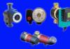
Well, now let’s practically try to repair the LED flashlight. To begin with, I will give a simplified electrical diagram of a flashlight with a rechargeable battery from the mains.
As you can see, the scheme is simple. Main elements: current-limiting capacitor, rectifier diode bridge with four diodes, battery, switch, super-bright LEDs, LED to indicate flashlight battery charging.
Well, now, in order, about the purpose of all the elements in the flashlight.
Current limiting capacitor. It is designed to limit the battery charging current. Its capacity for each type of flashlight may be different. A non-polar mica capacitor is used. The operating voltage must be at least 250 volts. In the circuit it must be bypassed, as shown, with a resistor. It serves to discharge the capacitor after you remove the flashlight from the charging outlet. Otherwise, you may get an electric shock if you accidentally touch the 220 volt power terminals of the flashlight. The resistance of this resistor must be at least 500 kOhm.
The rectifier bridge is assembled on silicon diodes with a reverse voltage of at least 300 volts.
To indicate the charging of the flashlight battery, a simple red or green LED is used. It is connected in parallel to one of the diodes of the rectifier bridge. True, in the diagram I forgot to indicate the resistor connected in series with this LED.
It makes no sense to talk about the other elements; everything should be clear anyway.
I would like to draw your attention to the main points of repairing an LED flashlight. Let's look at the main faults and how to fix them.
1. The flashlight stopped shining. There aren't many options here. The reason may be the failure of super-bright LEDs. This can happen, for example, in the following case. You put the flashlight on charge and accidentally turned on the switch. In this case, a sharp jump in current will occur and one or more diodes of the rectifier bridge may be broken. And behind them, the capacitor may not be able to withstand it and will short out. The voltage on the battery will increase sharply and the LEDs will fail. So, under no circumstances turn on the flashlight while charging unless you want to throw it away.
2. The flashlight does not turn on. Well, here you need to check the switch.
3. The flashlight discharges very quickly. If your flashlight is “experienced”, then most likely the battery has reached its service life. If you actively use the flashlight, then after one year of use the battery will no longer last.
4. The flashlight is not charging. The charging indicator LED does not light up. Disassemble the flashlight and check the electrical wiring for breaks. If no break is found, then inspect the current-limiting capacitor. It may appear swollen or intact. In any case, it must be replaced, as it may have an internal break. Install with such a capacity and an operating voltage of at least 250 volts. If the capacitor is damaged, check all diodes of the rectifier bridge
As you can see, the scheme is simple. Main elements: current-limiting capacitor, rectifier diode bridge with four diodes, battery, switch, super-bright LEDs, LED to indicate flashlight battery charging.

Well, now, in order, about the purpose of all the elements in the flashlight.
Current limiting capacitor. It is designed to limit the battery charging current. Its capacity for each type of flashlight may be different. A non-polar mica capacitor is used. The operating voltage must be at least 250 volts. In the circuit it must be bypassed, as shown, with a resistor. It serves to discharge the capacitor after you remove the flashlight from the charging outlet. Otherwise, you may get an electric shock if you accidentally touch the 220 volt power terminals of the flashlight. The resistance of this resistor must be at least 500 kOhm.

The rectifier bridge is assembled on silicon diodes with a reverse voltage of at least 300 volts.
To indicate the charging of the flashlight battery, a simple red or green LED is used. It is connected in parallel to one of the diodes of the rectifier bridge. True, in the diagram I forgot to indicate the resistor connected in series with this LED.
It makes no sense to talk about the other elements; everything should be clear anyway.
I would like to draw your attention to the main points of repairing an LED flashlight. Let's look at the main faults and how to fix them.
1. The flashlight stopped shining. There aren't many options here. The reason may be the failure of super-bright LEDs. This can happen, for example, in the following case. You put the flashlight on charge and accidentally turned on the switch. In this case, a sharp jump in current will occur and one or more diodes of the rectifier bridge may be broken. And behind them, the capacitor may not be able to withstand it and will short out. The voltage on the battery will increase sharply and the LEDs will fail. So, under no circumstances turn on the flashlight while charging unless you want to throw it away.

2. The flashlight does not turn on. Well, here you need to check the switch.
3. The flashlight discharges very quickly. If your flashlight is “experienced”, then most likely the battery has reached its service life. If you actively use the flashlight, then after one year of use the battery will no longer last.

Problem 1: The LED flashlight does not turn on or flickers when working
As a rule, this is the cause of poor contact. The easiest way to treat it is to tighten all the threads tightly.
If the flashlight doesn't work at all, start by checking the battery. It may be discharged or damaged.

Unscrew the back cover of the flashlight and use a screwdriver to connect the housing to the negative terminal of the battery. If the flashlight lights up, then the problem is in the module with the button.
90% of the buttons of all LED lights are made according to the same scheme:
The button body is made of aluminum with a thread, a rubber cap is inserted there, then the button module itself and a pressure ring for contact with the body.

The problem is most often solved by a loose clamping ring.
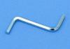
To fix this problem, just find round pliers with thin tips or thin scissors that need to be inserted into the holes, as in the photo, and turned clockwise.
If the ring moves, the problem is fixed. If the ring stays in place, then the problem lies in the contact of the button module with the body. Unscrew the clamping ring counterclockwise and pull the button module out.
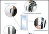
Poor contact often occurs due to oxidation of the aluminum surface of the ring or border on the printed circuit board (indicated by arrows)

Simply wipe these surfaces with alcohol and functionality will be restored.
Button modules are different. Some have contact through the printed circuit board, others have contact through the side petals to the flashlight body.
Just bend this petal to the side so that the contact is tighter.
Alternatively, you can make a solder from tin so that the surface is thicker and the contact is pressed better.
All LED lights are basically the same
The plus goes through the positive contact of the battery to the center of the LED module.
The negative goes through the body and is closed with a button.
It would be a good idea to check the tightness of the LED module inside the housing. This is also a common problem with LED lights.

Using round nose pliers or pliers, rotate the module clockwise until it stops. Be careful, it is easy to damage the LED at this point.
These actions should be quite enough to restore the functionality of the LED flashlight.
It’s worse when the flashlight works and the modes are switched, but the beam is very dim, or the flashlight doesn’t work at all and there’s a burning smell inside.

Problem 2. The flashlight works fine, but is dim or does not work at all and there is a burning smell inside

Most likely the driver has failed.
The driver is an electronic circuit on transistors that controls the flashlight modes and is also responsible for a constant voltage level, regardless of battery discharge.
You need to unsolder the burnt driver and solder in a new driver, or connect the LED directly to the battery. In this case, you lose all modes and are left only with the maximum one.
Sometimes (much less often) the LED fails.
You can check this very simply. Apply a voltage of 4.2 V/ to the contact pads of the LED. The main thing is not to confuse the polarity. If the LED lights up brightly, then the driver has failed, if vice versa, then you need to order a new LED.
Unscrew the module with the LED from the housing.
Modules vary, but as a rule, they are made of copper or brass and
The weakest point of such flashlights is the button. Its contacts oxidize, as a result of which the flashlight begins to shine dimly, and then may stop turning on altogether.
The first sign is that a flashlight with a normal battery shines dimly, but if you click the button several times, the brightness increases.

The easiest way to make such a lantern shine is to do the following:
1. Take a thin stranded wire and cut off one strand.
2. We wind the wires onto the spring.
3. We bend the wire so that the battery does not break it. The wire should protrude slightly
above the twisting part of the flashlight.
4. Twist tightly. We break off (tear off) the excess wire.
As a result, the wire provides good contact with the negative part of the battery and the flashlight
will shine with proper brightness. Of course, the button is no longer available for such repairs, so
Turning on and off the flashlight is done by turning the head part.
My Chinese guy worked like this for a couple of months. If you need to change the battery, the back of the flashlight
should not be touched. We turn our heads away.

RESTORING THE OPERATION OF THE BUTTON.
Today I decided to bring the button back to life. The button is located in a plastic case, which
It's just pressed into the back of the light. In principle, it can be pushed back, but I did it a little differently:
1. Use a 2 mm drill to make a couple of holes to a depth of 2-3 mm.
2. Now you can use tweezers to unscrew the housing with the button.
3. Remove the button.
4. The button is assembled without glue or latches, so it can be easily disassembled with a stationery knife.
The photo shows that the moving contact has oxidized (a round thing in the center that looks like a button).
You can clean it with an eraser or fine sandpaper and put the button back together, but I decided to additionally tin both this part and the fixed contacts.

1. Clean with fine sandpaper.
2. Apply a thin layer to the areas marked in red. We wipe off the flux with alcohol,
assembling the button.
3. To increase reliability, I soldered a spring to the bottom contact of the button.
4. Putting everything back together.
After repair, the button works perfectly. Of course, tin also oxidizes, but since tin is a fairly soft metal, I hope that the oxide film will be
easy to break down. It’s not for nothing that the central contact on light bulbs is made of tin.

IMPROVING FOCUS.
My Chinese friend had a very vague idea of what a “hotspot” was, so I decided to enlighten him.
Unscrew the head part.
1. There is a small hole in the board (arrow). Use an awl to twist out the filling.
At the same time, lightly press your finger on the glass from the outside. This makes it easier to unscrew.
2. Remove the reflector.
3. Take ordinary office paper and punch 6-8 holes with an office hole punch.
The diameter of the holes in the hole punch matches perfectly with the diameter of the LED.
Cut out 6-8 paper washers.
4. Place the washers on the LED and press it with the reflector.
Here you will have to experiment with the number of washers. I improved the focusing of a couple of flashlights in this way; the number of washers was in the range of 4-6. The current patient required 6 of them.

INCREASE THE BRIGHTNESS (for those who know a little about electronics).
The Chinese save on everything. A couple of extra details will increase the cost, so they don’t install it.
The main part of the diagram (marked in green) may be different. On one or two transistors or on a specialized microcircuit (I have a circuit of two parts:
inductor and a 3-leg IC similar to a transistor). But they save on the part marked in red. I added a capacitor and a pair of 1n4148 diodes in parallel (I didn't have any shots). The brightness of the LED increased by 10-15 percent.
1. This is what the LED looks like in similar Chinese ones. From the side you can see that there are thick and thin legs inside. The thin leg is a plus. You need to be guided by this sign, because the colors of the wires can be completely unpredictable.
2. This is what the board looks like with the LED soldered to it (on the back side). Green color indicates foil. The wires coming from the driver are soldered to the legs of the LED.
3. Using a sharp knife or a triangular file, cut the foil on the positive side of the LED.
We sand the entire board to remove the varnish.
4. Solder the diodes and capacitor. I took the diodes from a broken computer power supply, and soldered the tantalum capacitor from some burnt-out hard drive.
The positive wire now needs to be soldered to the pad with the diodes.

As a result, the flashlight produces (by eye) 10-12 lumens (see photo with hotspots),
judging by the Phoenix, which produces 9 lumens in minimum mode.
With the release of iOS 7, Apple phones now have a standard function for controlling the rear LED; before that, users had to download third-party applications. Most often it is used for illumination at night, so if the flashlight on the iPhone does not work, it becomes difficult to move in the dark.
There are several ways to check if the flashlight is not working on Apple devices:
- Through the lock panel.
- Via the quick access panel.
- Using special applications.

Often, users have problems using the LED backlight, and then they download programs designed specifically to restore the functionality of the module. Even if they do not help you use the desired function, you should pay attention to malfunctions that may prevent this.
If the flashlight on your iPhone does not turn on, this could be due to a number of reasons:
- Damage to the camera cable during a previous repair (the camera and LED are in the same module).
- Loss of tightness due to prolonged exposure of the device to water.
- Falling or mechanical damage to parts.
- Roughly and forcefully pressing the camera icon or turning on the LED flash function.
- Incomplete or incorrect installation of the program to use the backlight.
- Inappropriate iOS firmware.
As in most devices, the flash when using a camera operates from the same parts and according to a similar principle. That is why the reason may be the introduction of an unqualified technician into the operation of the device: if the parts malfunction or are damaged, neither the flash nor the flashlights will be available to the user.
Note! Most likely, the icon of the same name will be gray in the bottom menu.

How to fix the problem
When the flashlight does not work, you can use one of the tips from experienced craftsmen:
- Check the operation of the cameras, front and rear. The LED module is tied to these parts and will not start without them.
- Reboot your iPhone.
- Switch to different cameras until the black screen (if there is one) disappears.
- Force stop camera apps through settings.
- Perform a forced reboot of the device.
- Reset the settings to factory settings (read).
- Restore the device via DFU - emergency mode.
If the malfunction is caused by a software glitch, you need to go to Settings and do a reset, having first created a system backup and copied all the necessary files (videos, photos), otherwise they will be erased and it will be problematic to restore them.
A hard reset can also be done through iTunes, but this will require a connection to a PC via a cable, as well as having the program installed on the computer.
The situation is worse if resetting through settings and/or Hard Reset in other ways does not help. In this case, you will have to contact the service and probably replace the non-working iPhone parts.
If a software failure is not the cause of the module's inoperability, it is a matter of mechanical damage to the spare parts. They must be replaced to restore functionality.

Controlling the flashlight via the quick access panel
The iOS control center is a universal access panel where you can use almost all iPhone functions, including the backlight. To turn the flashlight on or off on an iPhone 5 or any other model, you need to do the following:
- Swipe up and down on the screen.
- Find the lantern icon and click on it. To deactivate, simply select this icon again.
If the quick access panel does not have a button for controlling the light, you can add it in the corresponding section of the settings.

Control via lock screen
This method is only suitable for controlling the built-in lighting function, not the software one. After clicking on the “lock” button located on the top or side panel of the device, the lock screen appears. To quickly turn on the flashlight, just click on the camera icon. You can turn off the flashlight in the same way.
The iPhone will have to be repaired if the flashlight does not work, only in a workshop, because if you independently interfere with the functioning of the device, opening the case and replacing parts, you can only aggravate the situation if you do not have the appropriate experience and knowledge. Most likely you will have to replace the camera module, since the LED is tied to it.
The owner himself can only diagnose and repair without disassembling the device, and in most cases the problem can be fixed without visiting a technician.
Third party programs
For those who for some reason cannot use the built-in lighting control functions, there is special software.
Flashlight by Rick
Flashlight by rik is one of the most popular flashlight apps on iPhone. It can be downloaded for free, and the utility will take up only 100 kB of RAM. When used, the owner will be able to enjoy bright light, while it allows you to use the flashlight even if it is not turned on in the standard way.
In addition, you can change the blinking frequency of the LED, you can create a stoboscope effect. The program has a bunch of other settings, you should “play around” with them and choose the operating mode that suits the situation.
Flashlight XS
This application is used to send an emergency SOS signal, as it turns on the backlight with intermittent flashing. If a regular flashlight doesn't work, you can use it when there are no other options. The path in the dark will be well lit.
Sos my location – personal safety app
There is not only a good supply of light, but also other useful functions: a GPS tracker and an SOS alarm. The program can be installed on both iPhone and iPad, so it is in great demand among owners of Apple equipment.

Conclusion
If the flashlight on the iPhone 4, 5, 5s or any other Apple brand model does not work, most often it is enough to download a special application, since problems with the standard backlight are quite common.
In 90% of cases, rebooting the smartphone helps, and for the average user, this is enough to use the lighting function without any problems. But if the functionality of the module cannot be restored using a third-party application, it is recommended that you contact a qualified technician for diagnosis and repair.
Video
Among the requests to the Fenix service center, the first place is the problem with the power button in the tail of the flashlight. If the light of the flashlight works intermittently, the LED lights up and turns off, it is most likely that the metal ring in the power button is not seated tightly.
To resolve the problem, do the following:
- Unscrew the tail part of the flashlight with the button.
- Inside you will see a silver ring with two holes.
- Take a special wrench or pliers.
- Place the tool in the holes and start screwing COUNTERCLOCK-WISE. If the ring is lost, it may cause the flashlight to not work properly.
- IMPORTANT: Do not use Loctite (or similar) to secure the rubber O-ring. To replace the button in the tail of the light, it should be possible to remove the O-ring for better access.
- It is recommended to periodically check how tight the metal ring is to ensure smooth operation of the flashlight.
NOTE: Not all Fenix flashlights have a metal ring in the power button. If your flashlight has a power button on the tail that looks like the one in the photo, follow the instructions above.
The flashlight does not turn on
The instructions for correcting the problem apply to all flashlights with a removable head and tail. These flashlights include Fenix PD35, UC35, PD32 and others. If you disassembled the flashlight, for example, to clean it, you might have mixed up the tail (with the power button) and the head (with the LED) parts. Some people do this not by mistake, but on purpose, to make the location of the clip more convenient. If the location of the tail and head sections is changed, the flashlight will not work.

Troubleshooting Guide
If your flashlight stops working, don't worry, the problem is likely easy to fix. Below is a summary of the troubleshooting steps.
Recheck your power supply
The first thing you should check if the flashlight won't turn on is to double check the power source. Even if you are sure that you are using new charged batteries or rechargeable batteries, replace them. This is a simple and easy step that can quickly fix the problem.
Cleaning contacts
The next step is to clean all parts of the flashlight that come into contact with the battery. Pay special attention to the terminals. It is best to use alcohol for this. It cleans most types of contaminants and evaporates quickly. Don't forget to clean the threads in the lantern and check the presence and condition of the O-ring. Be sure to lubricate the O-ring with silicone grease. Below is a video guide on how to clean the lantern.
Power button diagnostics
If your light has been cleaned and has new batteries, but it still doesn't work, you should check the power button on the tail. To do this, remove the tail switch and make sure the battery is installed correctly (polarity). Next, place a metal object (such as tweezers or a screwdriver) so that it simultaneously touches both the battery pole and the flashlight body. If the light comes on, then the problem is in the tail switch, if not, then the problem is with the head part of the lamp.

If the problem is related to the tail switch (the light of the flashlight turns on when the contact of the battery pole is shorted to the metal body of the flashlight), then it is necessary to carefully inspect it. First of all, make sure there are no foreign objects. Next, try tightening (if it does not fit tightly) the metal ring with holes counterclockwise, as described at the beginning of the article. Attach the tail switch to the light and check if the problem is resolved.

If the above methods do not help, you can always return the flashlight to service under warranty. Most problems can be solved simply using the methods described above.
As a final tip, you can try replacing the rubber pad in the tail derailleur. Spare pads are usually included with the flashlight. The replacement process is shown in detail in the video: