The light bulb in WoT is a tank commander's ability called the “sixth sense”.
Light bulb in WoT- This is the skill of a tank commander called the “sixth sense”. It lets you know when your tank was discovered. It works very simply; when your tank is detected, a light comes on. There are many types of light bulbs that can be found on the Internet. You can also install a mod so that when an enemy detects you, the light not only lights up, but is also accompanied by a sound signal and stays on for 10 seconds (approximately the time of the light).
Necessity.
The “sixth sense” skill is necessary on almost all tanks in the game, except for self-propelled guns, since they usually stand in the bushes behind allied lines. Particular attention should be paid to tank destroyers that shoot from an ambush, or light tanks that passively shine on the enemy (from the bushes), or heavy and slow tanks that can be covered by a barrage of artillery fire, some tanks easily penetrate and almost always save the player from the first shot the most skill. Experienced players can sometimes even understand without a light bulb that they have been exposed.
Example.

Let's take a look at the German premium tank destroyer E25. She has practically no armor, but she has a low silhouette, therefore, she has good camouflage, but this may not save her from an enemy projectile because she can also be exposed here, and the “sixth sense” skill will help E25 simply change her position to a more profitable one.

The Maus heavy tank also needs this skill. Although he has a lot of armor, although he can repel enemy shells with his powerful body, he can also be killed and even go unnoticed, or even worse, he can be covered by enemy artillery, and our light bulb can save us from all this, warning us in advance that the enemy discovered us.
Let's look into the issue of installing a 6 sense light bulb mod.
The sixth sense is a tank commander perk that you should level up very first, since your “survivability” in battle largely depends on whether you know that your opponents can see you or not. And the lamp just helps you determine whether your tank is lit up by enemies with a red dot on the minimap or not.
Attention! If the corresponding commander skill 6 sense is not fully upgraded, mods for changing the lamp will not work! Keep this in mind!
How to install 6th sense?
In fact, it doesn’t take much effort to install a light bulb, since in my opinion this is the simplest mod for World of Tanks. There are three ways.
1) How to change a light bulb without XVM
The method is outdated and inconvenient, but is still used by some modders. The installation is extremely simple and boils down to the fact that the downloaded archive with the mod must be placed in a special folder with the game:
World_of_Tanks/res_mods/ 1.6.0.0
Such an archive usually contains not pictures, but SWF files and folders that allow you to create animated lamps, new sounds, etc.
In most cases, one image of a lamp is enough, so let's move on to the second point.
2) How to install a light bulb in World of Tanks 1.6.0.0 using the XVM mod?
First you need. You can simply drop the folder from the archive into the game and not bother with its advanced functionality and complex config, since basic things will work right away (including a simple replacement of a light bulb), and this is exactly what we need within the framework of these instructions.
Also, do not be afraid for your precious FPS, which will not suffer, again, if you only need XVM to install a lamp - do not enable additional “heavy” features of the mod, such as an informative minimap (the most power-hungry element) and everything will be fine. Checked personally.
After installing the XVM mod, our new light bulb is located in the specified path: \World_of_Tanks\res_mods\mods\shared_resources\xvm\res.
Now we can upload any image in PNG format (!!!) and the light bulb will work.
Important! The name of your lamp file must be SixthSense.png. When saving a new lamp in this folder, you must overwrite the old one (or first delete it, then place a new image there).
This method is good because you can use any image you like, even your own photo, and then the most pleasant and charming person on earth will notify you about the exposure
Preparing the image for the lamp
The easiest way is to download a ready-made image. For this you can use, but if this is not enough, then go to Google image search and enter the following phrases there:
- wot light bulb png
- sixth sense wot png
- and so on until you find something you like...
You can try different queries, but the most important thing is that at the end there is " png" - this will give the search engine a command to look for pictures of this particular format and in 90% of cases they will be on a transparent background, which looks much more beautiful in the game.
What to do if not a single lamp card found fits?
Let's make a lamp ourselves, using the example of a sticker from VKontakte in the form of a funny potato:
To get this image, the easiest way is to look at the VKontakte element code. This can be done, for example, using the Firebug extension for all popular browsers. It can take a very long time to describe how to use it, so look for information on other sites.
Let's look at the code:

It follows that the image along this path is used http://vk.com/images/stickers/147/128.png, size 128x128 pixels.
The following sizes are also available to us:
- http://vk.com/images/stickers/147/64.png- 64x64 pixels, suitable for small resolutions;
- http://vk.com/images/stickers/147/128.png - ideal format 128x128 pixels, for medium resolutions, suitable for most;
- http://vk.com/images/stickers/147/256.png- 256x256 pixels;
- http://vk.com/images/stickers/147/512.png- 512x512 pixels, I do not recommend using it, as it will cover most of the screen.
You can already use these images as a lamp. To do this, save what you need to a folder \World_of_Tanks\res_mods\mods\shared_resources\xvm\res by renaming the file itself to SixthSense.png.
This is what it looks like in the game:

But let's assume that our picture was not originally on a transparent background. What to do in this case?
You can do it yourself, having a graphics editor at hand, such as Photoshop (you can easily find a free version with a crack, search on torrents).
1) Step one - open the image in Photoshop, click on the "Magic Wand" tool:

Then click on an empty area of the image. It is worth noting here that it is much more convenient when the background of the picture is uniform, so that there is no interference during “smart” selection:

Then we simply delete the background using the DELETE button on the keyboard:

Done, the image can be saved as SixthSense.png.
If the background of the image was initially non-uniform, then you can cut out the desired part using the Lasso tool:

With its help, we simply circle the desired part of the image:

If your hand twitched during the process and you made a crooked selection, you can quickly reset it with the CTRL+D combination. It is also important to “close” the selection circle. After several workouts, you can achieve the desired result.
If it doesn’t work with the lasso, you can select the element using standard means (square or oval selection) and then “sand it up” using the eraser.
So, in the example above, the Serb’s face was highlighted. Now click:
- CTRL+C - copy the selection to the clipboard.
- CTRL+N - create a new empty file, click OK. The main thing here is that the background is transparent. Also pay attention to the size of the new file - by default, the size of the selected fragment from the clipboard is taken, where we copied it in the first step.
- In the new file, press CTRL+V - insert our “clipping”.
It should look like this:

Here you can correct the edges with an eraser, add inscriptions, effects, etc.
Finally, click the following - File > Save for WEB:

In the window that appears on the right, select the PNG format and check the Transparency box:

Save the file as SixthSense.png to a folder \World_of_Tanks\res_mods\mods\shared_resources\xvm\res.
Fluorescent lamps (FLLs) are widely used to illuminate both large areas of public premises and as household light sources. The popularity of fluorescent lamps is largely due to their economic characteristics. Compared to incandescent lamps, this type of lamp has high efficiency, increased light output and a longer service life. However, a functional disadvantage of fluorescent lamps is the need for a starting starter or a special ballast (ballast). Accordingly, the task of starting the lamp when the starter fails or is absent is urgent and relevant.
The fundamental difference between an LDS and an incandescent lamp is that the conversion of electricity into light occurs due to the flow of current through mercury vapor mixed with an inert gas in a bulb. Current begins to flow after breakdown of the gas by high voltage applied to the electrodes of the lamp.
- Throttle.
- Lamp bulb.
- Luminescent layer.
- Starter contacts.
- Starter electrodes.
- Starter housing.
- Bimetallic plate.
- Lamp filaments.
- Ultraviolet radiation.
- Discharge current.
The resulting ultraviolet radiation lies in the part of the spectrum invisible to the human eye. To convert it into a visible light flux, the walls of the bulb are coated with a special layer, a phosphor. By changing the composition of this layer, you can obtain different light shades.
Before the direct launch of the LDS, the electrodes at its ends are heated by passing a current through them or due to the energy of a glow discharge.
High breakdown voltage is provided by ballasts, which can be assembled according to a well-known traditional circuit or have a more complex design.
Starter operating principle
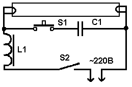
In Fig. Figure 1 shows a typical connection of an LDS with a starter S and a choke L. K1, K2 – lamp electrodes; C1 is a cosine capacitor, C2 is a filter capacitor. A mandatory element of such circuits is a choke (inductor) and a starter (chopper). The latter is often used as a neon lamp with bimetallic plates. To improve the low power factor due to the presence of inductor inductance, an input capacitor is used (C1 in Fig. 1).

Rice. 1 Functional diagram of LDS connection
The LDS startup phases are as follows:
1) Warming up the lamp electrodes. In this phase, the current flows through the circuit “Network – L – K1 – S – K2 – Network”. In this mode, the starter begins to close/open randomly.
2) At the moment the circuit is broken by the starter S, the magnetic field energy accumulated in the inductor L is applied in the form of high voltage to the electrodes of the lamp. An electrical breakdown of the gas inside the lamp occurs.
3) In breakdown mode, the lamp resistance is lower than the resistance of the starter branch. Therefore, the current flows along the circuit “Network – L – K1 – K2 – Network”. In this phase, inductor L acts as a current-limiting reactor.
Disadvantages of the traditional LDS starting circuit: acoustic noise, flickering with a frequency of 100 Hz, increased start-up time, low efficiency.
Operating principle of electronic ballasts
Electronic ballasts (EPG) use the potential of modern power electronics and are more complex, but also more functional circuits. Such devices allow you to control the three startup phases and adjust the light output. The result is longer lamp life. Also, due to the lamp being powered with a current of a higher frequency (20÷100 kHz), there is no visible flicker. A simplified diagram of one of the popular electronic ballast topologies is shown in Fig. 2.

Rice. 2 Simplified circuit diagram of electronic ballasts
In Fig. 2 D1-D4 – mains voltage rectifier, C – filter capacitor, T1-T4 – transistor bridge inverter with transformer Tr. Optionally, the electronic ballast may contain an input filter, a power factor correction circuit, additional resonant chokes and capacitors.
A complete schematic diagram of one of the typical modern electronic ballasts is shown in Fig. 3.

Rice. 3 Diagram of BIGLUZ electronic ballasts
The circuit (Fig. 3) contains the main elements mentioned above: a bridge diode rectifier, a filter capacitor in the DC link (C4), an inverter in the form of two transistors with wiring (Q1, R5, R1) and (Q2, R2, R3), inductor L1, transformer with three terminals TR1, trigger circuit and lamp resonant circuit. Two windings of the transformer are used to turn on transistors, the third winding is part of the resonant circuit of the LDS.
Methods for starting LDS without specialized ballasts
When a fluorescent lamp fails, there are two possible reasons:
1) . In this case, it is enough to replace the starter. The same operation should be carried out if the lamp flickers. In this case, upon visual inspection, there are no characteristic darkening on the LDS flask.
2) . Perhaps one of the electrode threads has burned out. Upon visual inspection, darkening may be noticeable at the ends of the bulb. Here you can use known starting circuits to continue operating the lamp even with burnt-out electrode threads.
For emergency starting, a fluorescent lamp can be connected without a starter according to the diagram below (Fig. 4). Here the user plays the role of starter. Contact S1 is closed for the entire period of lamp operation. Button S2 is closed for 1-2 seconds to light the lamp. When S2 opens, the voltage on it at the moment of ignition will be significantly higher than the mains voltage! Therefore, extreme caution should be exercised when working with such a scheme.

Rice. 4 Schematic diagram of starting an LDS without a starter
If you need to quickly ignite an LVDS with burnt filaments, then you need to assemble a circuit (Fig. 5).
Rice. 5 Schematic diagram of connecting an LDS with a burnt filament
For a 7-11 W inductor and a 20 W lamp, the C1 rating is 1 µF with a voltage of 630 V. Capacitors with a lower rating should not be used.
Automatic circuits for starting an LDS without a choke involve using an ordinary incandescent lamp as a current limiter. Such circuits, as a rule, are multipliers and supply the LDS with direct current, which causes accelerated wear of one of the electrodes. However, we emphasize that such circuits allow you to run even an LDS with burnt-out electrode threads for some time. A typical connection diagram for a fluorescent lamp without a choke is shown in Fig. 6.

Rice. 6. Block diagram of connecting an LDS without a choke

Rice. 7 Voltage on the LDS connected according to the diagram (Fig. 6) before start-up
As we see in Fig. 7, the voltage on the lamp at the moment of starting reaches the level of 700 V in approximately 25 ms. Instead of an HL1 incandescent lamp, you can use a choke. Capacitors in the diagram of Fig. 6 should be selected within 1÷20 µF with a voltage of at least 1000V. Diodes must be designed for a reverse voltage of 1000V and a current of 0.5 to 10 A, depending on the lamp power. For a 40 W lamp, diodes rated for current 1 will be sufficient.
Another version of the launch scheme is shown in Fig. 8.

Rice. 8 Schematic diagram of a multiplier with two diodes
Parameters of capacitors and diodes in the circuit in Fig. 8 are similar to the diagram in Fig. 6.
One of the options for using a low-voltage power supply is shown in Fig. 9. Based on this circuit (Fig. 9), you can assemble a wireless fluorescent lamp on a battery.

Rice. 9 Schematic diagram of connecting LDS from a low-voltage power source
For the above circuit, it is necessary to wind a transformer with three windings on one core (ring). As a rule, the primary winding is wound first, then the main secondary (indicated as III in the diagram). Cooling must be provided for the transistor.
Conclusion
If the fluorescent lamp starter fails, you can use an emergency “manual” start or simple DC power circuits. When using circuits based on voltage multipliers, it is possible to start a lamp without a choke using an incandescent lamp. When operating on direct current, there is no flicker or noise from the LDS, but the service life is reduced.
If one or two filaments of the cathodes of a fluorescent lamp burn out, it can continue to be used for some time, using the above-mentioned circuits with increased voltage.
Have you decided to install electrical wiring in your new dacha yourself or to upgrade the existing network in your apartment? Agree, there are nuances in this area that you should thoroughly understand for your own safety. In addition, self-made electricians must ensure the flawless operation of the devices.
We are ready to tell you in great detail how to connect a light bulb through a switch. In implementing such a solution, a number of practice-tested techniques are used, which you will become familiar with while reading the article.
Here you will find a lot of useful information. Possession of information will give both confidence and strength. Graphic materials and videos will help you thoroughly understand the issue.
Previously, before starting the installation of switches, lighting fixtures, connecting them to each other and the network, it is necessary to de-energize the 220V power supply to that part of the home wiring where electrical installation work is expected to be carried out.


Tool for getting the job done
In the process of performing electrical work, a home handyman will need a set of the following installation tools:
- Sharp knife.
- Pliers (pliers).
- Side cutters.
- Slotted screwdrivers, thin and medium, possibly Phillips medium.
Electrical tape may be required to insulate the wire connections inside the junction box or light housing. In these cases, it is recommended to use CB tape. Over time, it does not melt or stick to the constantly heating contacts it insulates, but only dries out. If necessary, crumble well with pliers.

Before you begin the simplest installation, draw a diagram for connecting electrical appliances in a way that will be clear to you, and think over the procedure
It’s great if you have a special one or wire cutters with slots for removing insulation. In the absence of such devices and a large amount of work, you can get by with a folk remedy by modifying the side cutters.
To do this, use a file to make opposite cuts in the cutting edges closer to the hinge, which together should form a hole slightly larger than the diameter of the exposed wire strand.
For new installations of home electrical lighting networks, it is recommended to use VVGng cables with single-wire copper, 1.5 sq. mm cross-section, in non-flammable insulation with conductors of different colors:
- blue – zero working,
- yellow with a green stripe along its length – zero protective (grounding),
- any other color - phase.
When installing, it is advisable to maintain a combination of color uniformity and their functional purpose. This requirement will protect and also simplify further maintenance of the electrical wiring.


If the design of the device allows, inside the switch itself, the phase wire is connected to the upper terminals, and all outgoing conductors are connected to the lower contacts. This rule applies to the arrangement of any electrical installation.
Due to design features, exceptions to the general rules are pass-through and crossover switches, which are discussed below.
Types of household switches
There are a wide variety of switches used in modern home interiors. A detailed description of the classification of light control devices is available on our website.

When choosing a home switch, pay more attention not to its design, but to functionality, strength of fastenings and reliability of electrical contacts
Based on the differences in their functionality, the following most common varieties are distinguished:
- Single-key switch– its mission is simple: “on/off”.
- Two-gang switch allows you to simultaneously control two independent lighting circuits.
- Three-key switch, accordingly, coordinates work in three directions.
- Switch-regulator (dimmer) not only turns it on and off, but also by pressing a key or turning the round knob that replaces it, smoothly adjusts the brightness of the lamps.
- Switch with regulator– a two- or three-key switch, which, in steps, by switching keys, controls the intensity of all light bulbs simultaneously.
- Single pass-through switch. The only key changes the phase between two wires. If voltage is applied to one, it is turned off from the other, and vice versa.
- Cross single switch. By changing the position of the key, it synchronously changes the direct connection of two lines to a cross one.
- Sensor switch. It has no levers - it starts and stops the flow of electricity by touching its surface with your fingers.
A motion sensor switch turns on the lamp automatically, reacting to a person passing by.
Types of lamps for home use
Tube progress keeps pace with switches. Their diversity is also impressive.

When purchasing an energy-saving light bulb, you should focus on well-known brands - after all, it should not only be efficient, but also last as long as possible
But here, too, some more popular types are defined:
- Incandescent lamps– rooted home light sources in a round glass bulb with a vacuum and a tungsten coil inside.
- Halogen lamps– the same incandescent lamps filled with a special gas. It increases service life and minimizes the size of their flasks. Disadvantage: When installing, you cannot touch the glass of the flask with your hands.
- Fluorescent daylight lamps– not very common at home, but also traditional lighting devices (hereinafter simply “fluorescent lamps”).
- Energy saving LED lamps, based on the name, they use the glow of groups of LEDs. They can be fixed into ordinary screw-in sockets (hereinafter simply “LED lamps”).
Energy-saving fluorescent light bulbs are increasingly replacing the usual ones. The operating principle is similar to fluorescent lamps. They are screwed in like incandescent lamps (hereinafter simply “energy-saving lamps”).
Ways to power a light bulb through a switch
Perhaps some of the schemes under consideration for the mutual connection of a household switch to a wall or ceiling light bulb will omit the details of supplying the neutral protective (grounding) wire. It seems that connecting it will not cause any difficulties.
In a standard electrical cable, this is a core with yellow insulation and a green stripe along it. The place where it is connected to the electrical appliance is indicated by a sign.
#1: The simplest connection of the lamp
The most basic thing is to connect the “on/off” lighting device to a single-key switch with two wires. Most of all it is suitable for a single single-lamp lamp.
When the old wiring has only two wires coming out of the ceiling or wall feeding the light electrical device, and the alteration is complicated, you can connect a lamp with more lamps. But with this connection, all the light bulbs of the lighting device will turn on simultaneously.
A classic single-key switch without upgrading the wiring can be easily replaced with a light dimmer switch (dimmer) made in a single unit. It is possible to purchase a device with a regulator like a key, or you can purchase it in the form of a round knob.
The characteristics of the dimmer must correspond to the power of the connected lamp. The only thing is that it cannot be used in conjunction with lighting fixtures equipped with energy-saving, LED or fluorescent lamps.
For standard installation in ordinary socket boxes, the industry has mastered the production of touch switches that have only “on/off” functions. They are also connected with two wires and can replace simple single-key ones.
#2: Separate switching on of chandelier lamps
Typically, three- and five-arm chandeliers are designed so that the lamps can be connected separately or together in groups (1+2/2+1; 2+3/3+2). This allows you to regulate the illumination of the space by the number of simultaneously working light bulbs.
In this case, you will need a two-key switch and an electrical wiring with at least three wires. By turning on one of the two or both keys at once, the brightness of the lighting fixture will be adjusted.
It is also used to control from one point the lighting of two, most often adjacent, rooms independently, for example, a toilet and a bathroom, a hallway and a storage room.
If, instead of the usual two-key switch, you use a two- or even three-key switch for a chandelier with separate controls built into the keys, then all its lamps will light at the same time, and their intensity can be controlled in stages by switching the keys.
#3: Controlling a five-arm chandelier
Where separate and simultaneous control of three independent lighting devices is necessary, a three-key switch is installed.
To surprise guests, you can connect a five-arm chandelier via a switch with three keys. True, a small alteration will be required on the terminals of the lamp itself. From a group of three linear wiring, one needs to be disconnected and used independently.
Then, using various combinations of pressing the keys of a three-key switch, it will be possible to turn on from one to five lamps at a time (1+2+2/2+2+1/2+1+2).
#4: Lamp – one, switches – two
What to do when the corridor is long and dark? This situation can be resolved by installing two lamps at once at different ends of the passage. The inconvenience of this method is the indefinite position of the “on/off” keys.
This lighting control technique is also applicable when moving up the stairs, in an attached garage (entrance from the house, exit through the gate and vice versa). An additional switch near the sleeping area will not be superfluous if the room is long enough.

When using non-standard lamp connection diagrams in practice, you should make sure of their feasibility, as this increases the length of the wires and the complexity of installation (+)
Is it possible to illuminate flights of stairs independently of each other, going up or down the steps? Additionally, you will need a single pass-through switch on the interfloor platform. By pressing just one key, it will simultaneously turn on the next lamp and turn off the previous one.
#5: Turning on a light bulb from different places
To control the luminaire from more than two centers, crossover single switches will be required in addition to the pass-through ones. Each new point - one at a time.
A lot of switches are convenient if living rooms open into a spacious hall at home. The occupants of any room will be able to independently turn on the lights at their doors and turn them off in all other places equipped with auxiliary switches.

With proper organization of installation locations for additional switches, in addition to ease of use of lighting, significant energy savings can be achieved
This method is also appropriate in rooms with a hotel-type layout - many doors opening into a long corridor.
#6: Connecting a chandelier with a fan
It is inconvenient to pull the pendant on a chandelier equipped with a fan to turn it on. This is also problematic when the ceiling is high.
It is easier to use the studied methods of separately connecting chandelier lamps. The fan is connected through one of the keys of a two- or three-key switch.
In the first option, the lamp can only burn completely. In the second, the light bulbs will light up in two groups.
#7: Built-in motion sensors
In itself it is already a device-switch. But we are interested in it precisely when it has a standard case and can be mounted in a socket box.
It turns out that it is connected to the gap in the phase conductor going to the lamp like a regular switch. But the problem is that the internal electronic circuit of such a device requires a full 220V power supply, which means one more wire, blue, zero.

In accordance with the principles of connecting the lamp, motion sensors (1) are connected through the switch. If there is a need for periodic constant operation of the lamp, a switch (2) is included in the circuit. If one sensor cannot cover a large room, then several are connected to the lamp. In this case, it is the sensors that play the role of a switch (3)
If you want to install a switch with a built-in motion sensor instead of a single-key one, you cannot do without replacing the two-wire wire stretching to it from the junction box with a three-wire one.
Conclusions and useful video on the topic
The videos will present practical techniques.
VIDEO No. 1 will show an example of a simple connection of a switch and a light bulb:
VIDEO No. 2 will help you master the skills of connecting and insulating wires:
VIDEO No. 3 will tell you how to connect chandeliers and more:
Manufacturers do not mark time in one place. They come up with all the new, more ingenious lighting devices. But no matter how cosmic the lamp may seem, there is always a simple way to connect it. Basic diagrams, rules for connecting light bulbs with switches, conditions for safe electrical work will remain standard for a long time.
When wiring is already present in an apartment or house and there is no need to connect additional light sources, then the question of how to connect a lamp is not relevant. But how can this work be done when the need arises? Here you can’t do without basic knowledge of electrical engineering and the ability to draw up a fundamental, seemingly elementary diagram.
All fluorescent light sources (housekeepers), incandescent lamps, LED lamps can be connected, as in principle all resistances present in the electrical circuit, in parallel, in series, mixed. A mixed connection is not used to connect lamps, since it is simply not necessary. But it’s worth paying attention to parallel and serial connections in more detail.
Serial and parallel connection of two or more light sources
In order to connect the simplest incandescent light bulb, as in principle any other, you need to connect one contact to phase and the other to zero, the most common alternating voltage in the CIS countries, 220 volts.
Parallel connection of lighting devices means connecting two or more sources of light flux in parallel, that is, some lamp contacts are connected only to phase, and all others only to zero, as shown in Figure 1.

A current will pass through each light bulb, which will depend on its power, just as the brightness of the light flux emitted by them will also depend on the power of each lamp. Naturally, the current I will be equal to the sum of all three currents, so the cross-sectional diameter of the main conductors should be chosen according to it. This connection is considered the most common and acceptable, since it will be possible, if necessary, to add light sources in the future and they will not affect those already installed.
With a series connection shown in the figure, the current flowing through one light bulb will depend on the power of each light source, and the voltage on them will be divided by the number of lamps and, for a given input voltage of 220 volts, will be equal to 110 volts on each light source.

This connection must be made with lamps that have equal power. This can be seen using the example of two incandescent lamps. Since if you connect one lamp of 20 Watt, and another, for example, of 200 Watt, then the lamp with a lower power will immediately fail, since the same current will pass through it as in the second lamp with a power of 200 Watt, and this is 10 times its face value. This connection can be used to increase the service life of incandescent lamps, for example, in entrances and staircases. By connecting two lamps of 220 volts and a power of, for example, 60 watts each, they will burn at half power and will last a very long time. Please note that this is only possible when connecting incandescent lamps. Connecting two or more LED lamps (luminaires) and energy-efficient lamps in series is not practical, since they already have a fairly long service life.
Connecting a lamp to one switch or several
How to connect a lamp through a switch? The main nuance when connecting is that the neutral power wire is directly connected to the 220 volt network, and the phase is broken through the switch. This is done so that you can safely solve problems with the lamp socket by turning off only the switch. If two switches are connected in series, then only when both keys are pressed will the lamp light up. These types of connection of light switches are very rarely used, only under certain individual conditions.

More interesting is the connection of the so-called pass-through switch.

The essence of this circuit for connecting one lamp is that the lamp can be turned on and off from both the first and second switches, regardless of the position of each of them. For example, this is convenient, say, in a long corridor, when entering it, a person presses the switch key 2, and calmly walks along the illuminated room, having reached the end of the corridor, there is no need to return to turn off the light, but he can lightly press switch 1, installed at the end corridor, turn off this light source. With this connection, the phase also passes through the switches.
Improving lighting by installing a motion sensor
The main function of installing a motion sensor and connecting it to the lighting system is to automatically turn on the lighting without pressing the light switch button. That is, a person entered the room or into the sensor trigger zone and the light turned on; after leaving, the light turned off on its own (automatically). When choosing a motion sensor, you must first take into account the maximum power of the lighting lamps.
 The connection diagram for the motion sensor is also not particularly difficult. It can be installed with or without a switch. Simply, when the switch contact is turned on, the motion sensor is removed from the lighting network, and the lighting device is turned on directly without a sensor.
In any case, when working with voltage, be sure to comply with safety requirements, and in particular:
- check the presence and absence of voltage on live elements that a person touches during installation;
- lighting power supply circuit breakers must be locked;
- carry out work with proper tools.
Video about connecting lamps