During the construction of private low-rise houses made of wood, concrete blocks or bricks, wooden floors are most often erected between floors. These structures, in comparison with alternative concrete slabs, have a number of advantages. Wooden floors do not overload the walls; during installation, they do not require the involvement of lifting equipment. In addition, they have high strength, durability and reasonable price. Installation of such ceilings is quite simple, so many home craftsmen perform it on their own.
floor structure
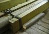
The basis of the wooden floor is the beams that are held on the load-bearing walls and serve as a kind of "foundation" for the rest of the structural elements. Since the beams during the operation of the floor will bear the entire load, special attention should be paid to their proper calculation.
For beams, massive or glued beams, logs, and sometimes boards (single or fastened in thickness with nails or staples) are usually used. For floors, it is desirable to use beams made of coniferous species (pine, larch), which are characterized by high bending strength. Hardwood beams work much worse in bending and can deform under load.
Draft boards (OSB, plywood) are fixed to the floor beams on both sides, on top of which the front cover is sewn. Sometimes the floor of the second floor is laid on logs, which are fixed on the beams.
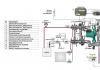
It is worth remembering that the wooden floor from the side of the first floor will be the ceiling, and from the side of the second floor (attic, attic) - the floor. Therefore, the upper part of the ceiling is sheathed with floor materials: grooved board, laminate, linoleum, carpet, etc. The lower part (ceiling) - clapboard, drywall, plastic panels, etc.
Due to the presence of beams, space is formed between the draft boards. It is used to give the overlap additional properties. Depending on the purpose of the second floor, heat-insulating or sound-proofing materials are laid between the floor beams, protected from moisture by waterproofing or vapor barrier.
In the event that the second floor is a non-residential attic that will not be heated, thermal insulation must be laid in the floor structure. For example, basalt wool (Rockwool, Parock), glass wool (Isover, Ursa), polystyrene, etc. A vapor barrier film (glassine, polyethylene and polypropylene films) is laid under the heat-insulating layer (from the side of the first heated floor).
If EPPS, which does not absorb water vapor, was used as thermal insulation, the vapor barrier film from the “pie” can be excluded. A layer of waterproofing film is laid on top of heat-insulating or sound-proof materials that absorb and can deteriorate from moisture. In the event that during the finishing the possibility of atmospheric moisture entering the attic was excluded, the insulation can not be protected by waterproofing.
If the second floor is planned as a heated and living space, then the “pie” of the floor does not need additional thermal insulation. However, in order to reduce the impact of noise that will occur when people move along the floor, a soundproof layer is laid between the beams (usually the usual heat-insulating materials are used).
For example, basalt wool (Rockwool, Parock), glass wool (Isover, Ursa), polystyrene foam, ZIPS sound-absorbing panels, soundproof membranes (Tecsound), etc. When using materials that can absorb water vapor (basalt wool, glass wool), a vapor barrier film is laid between the ground floor and the sound insulator, and waterproofing is placed over the sound insulator.

Fastening beams to the wall
Floor beams can be connected to walls in several ways.
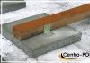
In brick or timber houses, the ends of the beams are led into grooves ("nests"). If beams or logs are used, then the depth of the beams in the walls should be at least 150 mm, if the boards - at least 100 mm.
Parts of the beams in contact with the walls of the "nest" are waterproofed by wrapping them with two layers of roofing material. The ends of the beams are cut at 60 ° and left uninsulated to allow free "breathing" of the wood.
When placed in a "nest", between the beam and the wall (on all sides), ventilation gaps of 30-50 mm are left, which are filled with thermal insulation (tow, mineral wool). The beam is supported on the base of the groove through an antiseptic and waterproofed wooden plank 30-40 mm thick. The sides of the groove can be covered with crushed stone or covered with cement mortar by 4-6 cm. Every fifth beam is additionally fastened to the wall with an anchor.

In wooden houses, beams are buried in the grooves of the walls by at least 70 mm. To prevent the appearance of squeaks, a waterproofing material is laid between the walls of the groove and the beam. In some cases, beams are cut into walls, making dovetail joints, etc.
Also, the beams can be fixed on the wall using metal supports - steel corners, clamps, brackets. They are connected to walls and beams with self-tapping screws or screws. This fastening option is the fastest and most technologically advanced, but less reliable than when beams are inserted into the grooves of the walls.

Calculation of floor beams
When planning the construction of the floor, first you need to calculate the design of its base, that is, the length of the beams, their number, the optimal section and the spacing. This will determine how safe your floor will be and what load it can withstand during operation.
Beam length
The length of the beams depends on the width of the span, as well as on the method of fastening the beams. If the beams are fixed on metal supports, their length will be equal to the width of the span. When embedded in the grooves of the walls, the length of the beams is calculated by summing up the span and the depth of inserting the two ends of the beam into the grooves.
Beam spacing
The distance between the axes of the beams is kept within 0.6-1 m.
Number of beams
The calculation of the number of beams is carried out as follows: they plan to place the extreme beams at a distance of at least 50 mm from the walls. The remaining beams are placed evenly in the span space, in accordance with the selected interval (pitch).
Beam section
Beams can have a rectangular, square, round, I-section. But the classic option is still a rectangle. Frequently used parameters: height - 140-240 mm, width - 50-160 mm.
The choice of the beam section depends on its planned load, the span width (on the short side of the room) and the spacing of the beams (step).
The load of the beam is calculated by summing the load of its own weight (for interfloor floors - 190-220 kg / m 2) with the temporary (operational) load (200 kg / m 2). Usually, for operating floors, the load is assumed to be 350-400 kg / m 2. For non-operated attic floors, you can take a smaller load, up to 200 kg / m 2. Special calculation is necessary if significant concentrated loads are expected (for example, from a massive bath, pool, boiler, etc.).
Beams are laid along a short span, the maximum width of which is 6 m. On a larger span, sagging of the beam is inevitable, which will lead to deformation of the structure. However, in this situation there is a way out. To support the beams on a wide span, columns and supports are installed.
The cross section of the beam directly depends on the width of the span. The larger the span, the more powerful (and durable) the beam must be chosen for overlapping. The ideal span for overlapping with beams is up to 4 m. If the spans are wider (up to 6 m), then non-standard beams with an increased cross section must be used. The height of such beams should be at least 1/20-1/25 of the span. For example, with a span of 5 m, beams with a height of 200-225 mm should be used with a thickness of 80-150 mm.
Of course, it is not necessary to independently perform beam calculations. You can use ready-made tables and diagrams that indicate the dependence of the dimensions of the beams on the perceived load and the width of the span.

After performing the calculations, you can proceed to the overlap device. Consider the entire technological process, starting with fixing the beams on the walls and ending with the finishing sheathing.
Wood flooring technology
Stage #1. Installation of floor beams
Most often, beams are installed with their introduction into the grooves of the walls. This option is possible when the installation of the floor is carried out at the stage of building a house.
The installation process in this case is as follows:
1. Beams are covered with antiseptics and flame retardants. This is necessary to reduce the tendency of wooden structures to rot and ensure fire safety.
2. The ends of the beams are cut at an angle of 60 °, they are painted with bituminous mastic and wrapped with roofing material in 2 layers (for waterproofing). In this case, the end should remain open, for the free exit of water vapor through it.
3. Installation begins with the installation of two extreme beams, which are placed at a distance of 50 mm from the walls (minimum).
The bars are inserted into the "nests" by 100-150 mm, leaving a ventilation gap between the wood and the walls of at least 30-50 mm.
4. To control the horizontalness of the beams, a long board is installed on their upper plane on the edge, and a bubble level is placed on top of it. To align the beams in level, wooden dies of different thicknesses are used, which are placed in the lower part of the groove on the wall. Dies must first be treated with bituminous mastic and dried.
5. To eliminate the creaking of the beam and block the access of cold air, the gap is filled with mineral insulation or tow.
6. On the laid control board lay out the rest, intermediate, beams. The technology for inserting them into the sockets of the walls is the same as for the installation of the extreme beams.
7. Every fifth beam is additionally fixed to the wall with an anchor.

When the house is already built, it is easier to install floor beams using metal supports. In this case, the installation process is as follows:
1. Beams are impregnated with flame retardants and antiseptics.
2. On the walls, at the same level, in accordance with the calculated step of the beams, fix the supports (corners, clamps, brackets). Fastening is carried out with self-tapping screws or screws, screwing them into the holes of the supports.
3. Beams are laid on supports and fixed with self-tapping screws.
Stage #2. Attachment of cranial bars (if necessary)
If it is more convenient to lay the “pie” of the floor structure from above, that is, from the side of the second floor, cranial bars with a section of 50x50 mm are stuffed along the edges of the beams on both sides. The bottom of the bars should be flush with the surface of the beams. The cranial bars are necessary in order to lay the rolling boards on them, which are the rough basis for the ceiling.
You can do without cranial bars if you hem the boards from the bottom, from the side of the first floor. In this case, they can be fastened directly to the beams using self-tapping screws (nails are not suitable, as they are difficult to drive vertically into the ceiling).
Stage #3. Fastening boards for the rough base of the ceiling
When mounting from the side of the second floor, roll-up boards are fixed to the cranial bars with nails or self-tapping screws (it is possible to use OSB, plywood).
When fastening the roll from the side of the first floor, the boards are fixed on the beams from below with the help of self-tapping screws. If necessary, lay a thick layer of insulation or soundproof material between the beams; the option of filing boards from below is preferable. The fact is that the cranial bars “eat up” part of the inter-beam space, and without their use, the thickness of the ceiling can be completely laid with insulating material.
Stage #4. Vapor barrier installation (if necessary)
The vapor barrier is laid in the floor structure in front of the insulation (which can also act as a sound insulator), if there is a risk of steam entering it or condensation. This happens if the overlap is arranged between floors, the first of which is heated, and the second is not. For example, an unheated attic or attic is being built above the first residential floor. Also, steam can penetrate into the floor insulation from damp rooms on the ground floor, for example, from the kitchen, bathroom, pool, etc.
The vapor barrier film is laid on top of the floor beams. The canvases are overlapped, leading the edges of the previous canvas to the next by 10 cm. The joints are glued with construction tape.
Stage #5. Thermal or sound insulation device
Between the beams, slab or roll heat or sound insulators are laid on top. Cracks and voids must be avoided, materials must fit snugly against the beams. For the same reason, it is undesirable to use trimmings that have to be joined together.
To reduce the occurrence of impact noise in the ceiling (with a residential upper floor), sound insulator strips with a minimum thickness of 5.5 mm are laid on the upper surface of the beams.
Stage #6. Laying waterproofing film
A waterproofing film is laid on top of the heat or sound insulating layer. It serves to prevent the penetration of moisture from the upper floor into the insulating material. If the upper floor is non-residential, that is, no one will wash the floors there and the penetration of atmospheric moisture will also be excluded, the waterproofing film can not be used.
The waterproofing film is laid in sheets, overlapping by 10 cm. The joints are glued with adhesive tape to prevent moisture from penetrating into the structure.
Stage #7. Fixing boards (plywood, OSB) for the subfloor
A draft base for the floor of the second floor is sewn along the beams from above. You can use ordinary boards, OSB or thick plywood. Fastening is carried out using self-tapping screws or nails.
Stage #8. Sheathing of the ceiling from below and from above with finishing coatings
Any suitable materials can be laid on top of the rough base from the bottom and top of the floor. On the upper side of the ceiling, that is, on the floor of the second floor, coatings of laminate, parquet, carpet, linoleum, etc. are arranged. When arranging the floor of a non-residential attic, draft boards can be left without sheathing.
Ceiling materials are sewn on the lower surface of the ceiling, which serves as the ceiling for the first floor: wooden lining, plastic panels, plasterboard structures, etc.

Operation of floors
If beams with a large margin of safety were used in the structure, laid with a small step, then such an overlap will not need to be repaired for a long time. But still, you need to check the beams for strength regularly!
If the beams are damaged by insects or as a result of waterlogging, they are strengthened. To do this, the weakened beam is removed, replaced with a new one, or reinforced with durable boards.