Underfloor heating using heating requires attention when developing a pipe laying scheme, calculating the number of circuits and the length of the pipeline, choosing a reinforced or lightweight floor option.
Related articles:

The fashion for such a method of heating a dwelling as a “warm floor” came to our homes recently - 15-20 years ago. Now it is available to anyone with an income above the average. Heating through the floor is advisable to use in cottages and individual houses.
Which pipes for underfloor heating are better to use
In order to conduct hot heating in the floor, pipes are evaluated according to three criteria:
- Thermal conductivity. The higher the conductivity of the pipe material, the less inert the heating will be.
- Flexibility. The good flexibility of the material will allow the pipes to be placed closer together.
- Durability and no leaks. A leak in the floor is a problematic situation that requires the dismantling of the structure.
You can immediately discard steel pipes, because. bending them in such volumes is not possible.
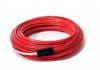
Metal-plastic pipe for underfloor heating
They are polyethylene pipes reinforced with a layer of aluminum, which provides the structure with the necessary rigidity and improves heat transfer properties. In addition, metal-plastic allows you to form the desired bends and angles.
We will evaluate the metal-plastic pipe on a five-point scale.
- thermal conductivity 4+;
- flexibility 5 points;
- durability 5 .
Metal-plastic pipes are light and easy to install, have an acceptable cost.
Polypropylene pipe for floor heating
Polypropylene pipes are considered a good budget option for organizing heating through the floor. Their significant disadvantage is the limited bending angle, which will not allow pipes to be placed closer to each other than 30 cm.
- thermal conductivity - 4;
- flexibility - 4;
- durability - 5.

XLPE pipes
Another option for polymer pipes. They consist of two layers of polyethylene, two adhesive layers and an oxygen barrier between them. They have good indicators of resistance to temperature influences. However, if you are not planning to heat your floor to 50 degrees C, this parameter is unlikely to be important.
- thermal conductivity - 4;
- flexibility - 4;
- durability - 5.
As can be seen from the evaluations, XLPE pipes generally correspond to polypropylene pipes.
Copper pipe for underfloor heating
The most exclusive option, both in terms of mounting complexity and financial costs. Of course, copper is one of the most thermally conductive metals. However, like any metal, it is subject to corrosion and oxidation, which affects durability and a higher likelihood of leaks compared to polymer pipes.
- thermal conductivity - 5;
- flexibility - 4;
- durability - 4.
Choosing a pipe laying scheme for a water-heated floor
In the practice of laying a warm floor, four schemes for the position of pipes have been fixed:
- spiral;
- snake;
- double snake;
- corner snake.
Spiral laying of a water floor
Laying in a spiral involves running a pipe along the perimeter of the room from the walls to the center and returning in the same way. This method allows you to heat the floor most evenly. On the one hand, this is a clear advantage. On the other hand, the heating of the zones immediately adjacent to the outer wall must be large, which is not provided by the conventional spiral method. To solve this problem, variations of spirals were invented:
- near the outer wall, the lines of the spiral are placed closer to each other than in other places. As a result, the center of the spiral shifts;
- division into two circuits: bordering the outer wall and the main one. First, the border contour is warmed up, from which water is directed to the main one.
The advantage of the helical scheme is the absence of strong bends, which makes it possible to use pipes made from materials with poor flexibility. The spiral laying method is suitable for rooms with a large area, the shape of which tends to be square.

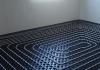
Snake styling
One of the popular laying schemes, which involves leading a pipe to one of the walls, usually to the outer one. From there, her path snakes from one wall to another in several turns. The snake ends at the wall opposite to the beginning.
This method implements the principle of enhanced heating of a part of the floor adjacent to the outer wall. Moving away from the beginning, the water cools. This equalizes the temperature of the floor in different parts of it to one value. The disadvantage of this scheme is the presence of numerous sharp bends in the places where the pipe turns. The serpentine laying method is used for rectangular rooms, as well as any complex geometric shapes.
Double snake
Unlike a simple snake, a double one - first moves in the same way from the outer wall to the opposite one with a large step between the pipes, and then returns back.
To insulate the area near the outer wall, an additional option is used: division into two circuits. The first borders on the outer wall, passing through which the water enters the main circuit. A more dense laying of pipes in close proximity to the wall will lead in this scheme to equalize the temperature throughout the floor.
corner snake
Corner snake is indispensable in rooms with two outer walls. This contour has a bit of a snake and a bit of a spiral. It follows the two outer walls, then turns around and walks back, continuing its path in a snake. Thus, the corner formed by the outer walls is the most heated. The opposite corner, respectively, is less heated.
Calculation of pipe parameters for underfloor heating
Proper equipment for a heating floor involves determining the laying step, calculating the diameter and length of the pipe, and heating circuits. This is necessary so that, firstly, the floor does not overheat, and, secondly, so that the water in the pipes has enough energy to overcome the entire distance.

Distance between pipes or laying spacing
The acceptable distance between the pipes is from 15 to 30 cm. A pipe with a diameter of 16-18 mm has the ability to heat up to 15 cm of the floor on both sides of itself. Thus, laying in increments of less than 15 cm only increases costs without significantly improving heating.
On the other hand, the heating also depends on the material of the pipe, the method of laying the floor, the material that was used for laying. The combination of these parameters can degrade thermal conductivity. Therefore, avoid a step of more than 25 cm.
The first lines near the outer wall are laid out closer: at a distance of 10 cm. The next ones - at a distance of 15, 20 or 25 cm.
The length and diameter of the pipe for underfloor heating
For floor heating, pipes with an external diameter of 16 mm, sometimes 18 mm, are used. The clearance of such pipes is 12 and 14 mm, respectively.
The length of the pipes is directly dependent on the area of the heated floor and is defined as the quotient of dividing the floor area (in meters) by the laying step (in meters). To the result you need to add 10% for pipe bends, as well as the distance from the collector and, if any, back.
Suppose a room has an area of 10.6 sq.m., of which 2.3 sq.m. we lay in steps of 0.1 m, and the rest 8.3 sq.m. - 0.2 m. The distance from the collector is 4 m, back - 1 m. We calculate:
2.3 / 0.1 + 8.3 / 0.2 = 64.5 m.
We take into account 10% of this length for pipe bends:
64.5 * 0.1 = 6.45 m.
We summarize the results, add 5 meters from and to the collector:
64.5 + 6.45 + 5 = 75.95 m.
Such a calculation is easy to do if you lay pipes over the entire floor area. However, in practice, in places where it is supposed to find heavy or bulky furniture that will not move, heating pad is not practical, and in cases of massive household items it is contraindicated. You can use the same calculation formula, while subtracting from the total area the area of \u200b\u200bsections where pipes will not be laid.
There is an alternative, more descriptive option without using the total area value. On a sheet in a cage, a room is schematically depicted in compliance with proportions and scale. Pipe laying is drawn, retreating 20 cm from the walls, and excluding those places where furniture is located (it can also be depicted in the diagram). Next, in accordance with the scale, calculate the length of the pipe. The result obtained is multiplied by 0.1. Both results are summed up.
Maximum contour length
The length of one circuit has a limitation associated with the throughput of the pipe and the amount of water that the main can pass per unit of time. As water moves through the pipes, its pressure begins to drop. After overcoming a certain critical threshold, water will lose the energy of motion.
The contour can have the following maximum length:
- for pipes with a diameter of 16 mm - 80 m;
- with a diameter of 18 mm - 100 m;
- with a diameter of 20 mm - 120 m.
Number of circuits
The number of circuits depends on the area to be heated and the length of each circuit. In order to make a calculation, determine the floor area in which the pipes will be laid. You can use the formula or the visual-scale method given above.
If the length of the circuit exceeds the maximum allowable dimensions (80, 100 or 120 m, depending on the diameter of the pipe), then this circuit is divided into two. This is the case for all premises.
When separating contours, the rule of "average value" is followed. The length of all contours should be approximately the same. Deviations of values should not exceed 1/3. The maximum number of circuits is limited by the capabilities that the collector node provides. In addition, an alternative calculation of the maximum number of circuits is carried out, based on the thermal power of the apparatus and the calculated heat transfer rate of the floor. On average, heat transfer with a laying step of 20 cm is 80 watts.
Yulia Petrichenko, expert
Suppose the heat transfer per square meter of the floor is 82 watts. The area of the premises is 10.6 m. The pumping and mixing unit has a thermal power of 8000 W.
Calculate the heat transfer of the entire floor in the room:
10.6*82=869.2W
Let's calculate the maximum number of contours:
8000 / 869,2 = 9,203
Thus, the collector serves up to 9 such circuits.
Online calculator for calculating pipes for underfloor heating
Underfloor heating pipes
The process of laying pipes is the most important and time-consuming. Often it is customary to fill the floor with pipes with a concrete screed. Recently, polystyrene-based styling has become increasingly popular.
Concrete water floor
- The floor is insulated with a layer of foam, polystyrene foam, polyethylene foam 10-20 mm high.
- Lay a layer of waterproofing film.
- A damper tape is laid along the edge of the perimeter to compensate for the expansion of the concrete screed.
- This is followed by a layer of reinforcing reinforcement with a mesh of 15 by 15 cm.
- Heating pipes are laid on the reinforcing mesh, which are attached to the mesh after 30-40 cm with special clamps. Laying is carried out according to the prepared scheme, retreating from the walls 20 cm.
- Carrying out pressing.
- Filling the floor with a mixture of sand concrete and a plasticizer 7 cm high. At the points of entry and exit of pipes from the screed, they are dressed in special metal casings to prevent deformation.
- The screed dries completely in 3 weeks, after which the floor covering is laid. It should be borne in mind that parquet does not like high temperatures, and carpet absorbs heat significantly.

Polystyrene installation
Refers to lightweight water floor systems, along with wood installation. Its basis is polystyrene plates 1x0.3 m, in which pipes and aluminum reflectors are laid. Polystyrene and aluminum allow even heat distribution.
- The floor, by analogy with concrete laying, is insulated with a layer of foam or other heat-insulating material.
- Polystyrene plates, which are called polyethylene film, are laid on the floor. A damper tape is placed between the plates and the wall.
- Aluminum plates are placed in the grooves of the plates. In the grooves of the plates - pipes.
- Pipes are connected to the collector. Carry out pressing.
- Lay a layer of foamed polystyrene.
- The floor is covered with gypsum-fiber moisture-resistant boards, on which the final floor covering is placed. To cover with linoleum, the seams on the slabs must be puttied.
Video "Laying piping for a warm water floor"
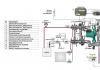
Pressurization of the underfloor heating system
Crimping is carried out to test the pipe for the possibility of leaks and its ability to pass water through its length.
Pressure testing of metal-plastic pipes is carried out with cold water at a pressure of 6 bar during the day. Pressure testing of polyethylene pipes takes place under the same pressure. Every half an hour, the pressure will drop, it will be raised to its previous level. The procedure is carried out 3 times, after which the pressure is raised to the initial one for the last time, and the system remains in this position for a day.
If the pressure in the pipes has not dropped and there are no leaks, then the test is considered passed. Having carried out the necessary calculations, it is not difficult to make a warm floor. This achievement of civilization, of course, is associated with additional costs, as well as the possibility of leaks.
What underfloor heating pipes do you use? What installation method was used? Tell us about your experience in the comments.
Expertise - Estimator
Ask an expert
Pipe for a warm water floor: which ones are better to use, how to calculate the length, choose a scheme, laying, video instruction, calculator - print version