The calculation of the heat of a warm floor is carried out taking into account heat losses through the building envelope and the usable area of the rooms. Errors in calculations affect the operation of the system, increase energy costs and house maintenance costs. Errors are due to the use of aggregated indicators. The effectiveness of insulation and the tightness of structures (foundation, load-bearing walls, ceilings, roofing, double-glazed windows, entrance doors) guarantees economical consumption of energy resources in the system.
A low-pressure heating circuit is able to optimize radiator heating or provide equivalent heating to the house and reduce energy costs.
The heating element and the coolant are design features that distinguish between water and electric underfloor heating. You can calculate the power of an electric underfloor heating using online calculators that are posted on specialized services on the Internet. In this article, we will take a closer look at the purpose and calculation of the power of water heated floors.
| Design features of a residential building | Underfloor heating power, W/m² (min/max) | |
| Additional (comfort) heating | ||
| Year of construction of the building - before 1996, climatic region - the European part of Russia | 80/120 | |
| Year of construction of the building - after 1996 (improved external insulation, thermal insulation of the basement and roof, double-glazed window), climatic region - the European part of Russia | 50/80 | |
| In rooms with wooden floors (subfloor and finished flooring) | 80/80 | |
| Loggias (balconies) with double glazing and insulation | 140/180 | |
| Main home heating | ||
| Kitchens, living rooms on the first and second floors (at least 3/4 of the heated area) | 150/∞ | |

Heat Q (W), which is generated by 1 square meter of a low-pressure water circuit, is the total flow of radiant (≈ 4.9 W/m²) and convective (≈ 6.1 W/m²) energy:
[ α l × (t floor - t ok) + α k × (t floor - t air) ] × S, (W), where
α l and α k - radiant and convective energy flows, W / m²;
floor t - flooring temperature, °C;
t ok - temperature of walls and ceiling, °C;
air t - room temperature, °C;
S - useful area of the circuit, m².

Explanation for schemes 1 and 2 for calculating the underfloor heating:
|
|

The calculation of underfloor heating determines the heat consumption of a residential building in accordance with regulatory documents on the thermal protection of buildings and building heat engineering:
Q \u003d (α l + α k) × S × (t floor - t air), (W);
t floor \u003d Q / [(α l + α k) × S] + t air, (° C);
at S \u003d 1m², t floor \u003d Q / (α l + α k) + t air, (°C).
When the room temperature rises by 1 degree, the heat from the floor surface is transferred to the air:
∆t = floor t - air t =1°C;
Q \u003d (α l + α k) × S × ∆t \u003d (4.9 + 6.1) × 1 × 1 \u003d 11 (W).

The ideal conditions under which the heat output of the water circuit on one square meter of underfloor heating to heat the air in the room by 1°C is 11 W/m². The higher the temperature in the room, the faster the room warms up and the lower the energy consumption of the coolant. The system of warm floors is preferable in order to heat insulated residential houses with permanent residence. The average allowable heat loss is 65 W/m².
To calculate the heat transfer of a warm floor, there are special programs that can be found on resources on the network. To clarify the issue, we suggest that you familiarize yourself with the video "Calculation of the heat transfer of a warm floor."
Heat carrier temperature
The temperature of the heat carrier in the circuit depends on the heat load, laying spacing, pipe diameter, screed thickness and flooring material. The minimum temperature values in the circuit are taken for parquet boards and small-piece wood products. Tiled, metlakh, ceramic tiles, porcelain stoneware, marble withstand the maximum permitted temperature of the coolant (55 ° C). Low-pressure heating circuits that are used in practice have an operating range of 45/35°C.
Sanitary standards define a comfortable (26 ° C) and permissible temperature limit for a human foot:
- 28°C in living rooms for permanent residence;
- 35°C along the perimeter of the load-bearing walls of a residential building;
- 33°C for kitchens, baths and sanitary rooms.

Underfloor heating bases
The type of overlap affects the materials and choice of layer thicknesses above and below the pipe. The basis for underfloor heating is cement screeds and flooring systems made of polystyrene or wooden shell boards. The aluminum profile in the rack modules serves as wood insulation from direct contact with the heating element and for fixing pipes.
Related article:
The layout of the pipes of the contour on concrete is arranged in the body of the concrete screed. The volume of material and installation calculations for underfloor heating are determined after preliminary marking of the surface (hydraulic or). The layout plan is carried out on paper (scale 1:50). The accuracy with which the calculation is carried out depends on the consumption of material and the speed of work.

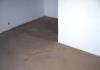
The surface cleaned and treated with a polymer primer is leveled in advance, waterproofing is done on the ground and on the first floors. Paste the walls around the perimeter with a damper tape to a height that will go under the screed (with a small margin). The heat-insulating material with a foil base shields the specific heat flux upwards in a given direction. Heat loss through the foil does not exceed 5%.
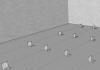
The reinforcement is laid on top of the insulation, the frame stiffens the screed and allows you to achieve the correct fixation of the step. The pipe circuit is laid out, fixed, the circuit is tested under pressure and filled with a screed solution.

Lightweight modular systems are used for wooden structures (subfloor or logs) that do not have the ability to withstand high static loads.
Calculations of pipes for a water-heated floor (length, diameter, pitch and laying methods and pipes)
The limited length of the low-pressure heating circuit is due to the "closed loop" effect, in which the pressure loss exceeds 20 kPa (0.2 bar). An increase in pump power is not an option in this case - the resistance will increase in proportion to the increase in pressure.

The estimated length of pipes for underfloor heating is determined by the formula:
L = (S/a×1.1) + 2c, (m), where
L - contour length, m;
S - area, contour, m²;
a - laying step, m;
1.1 - increase in the size of the bending step (margin);
2c - the length of the supply pipes from the collector to the circuit, m.
Important! The useful area of the room takes into account the area of the contour with the addition of half the pipe pitch.

In concrete screed
The heating circuit is laid, stepping back 0.3 m from the walls. Take into account the open floor area that transmits a uniform radiation flux. Experts do not recommend mounting the heating circuit in places where furniture is placed. Long-term static loading can cause pipe deformation.
With a large area of \u200b\u200bthe room, the heating circuit is divided into sectors. The basic rules for zoning are the aspect ratio of 1/2, the heating of the area of one sector is not more than 30 m² and the observance of the same length and diameter for the circuits of one collector.

Table 2. The ratio of the lengths and diameters of the pipes of the circuit:
| Diameter, mm | Pipe material | Recommended contour length, m |
| 16 | metal-plastic | 80 ÷ 100 |
| 18 | cross-linked polyethylene | 80 ÷ 120 |
| 20 | metal-plastic | 120 ÷ 150 |
The diameter and pitch of the pipe layout depends on the heat load, purpose, size and geometry of the room. The heat distribution zone is proportional to the radius of the pipe. The pipe heats a section of the floor in each direction from the center of the pipe. Balanced pipe pitch: Dy 16 mm - 0.16 m; 20 mm - 0.2 m; 26 mm - 0.26 m; 32 mm - 0.32 m.

The passport data of the products indicate the maximum throughput of the pipes, on the basis of which the linear pressure change is calculated. The optimal value of the coolant velocity in the pipes is 0.15 ÷ 1 m/s.
Table 3 The dependence of the step on the area and load of the sector:
| Diameter, mm | Distance along the axes (pipe pitch), m | Optimum load, W/m² | Total (or divided into sections) useful area of the premises, m² |
| 16 | 0,15 | 80 ÷ 180 | 12 |
| 20 | 0,20 | 50 ÷ 80 | 16 |
| 26 | 0,25 | 20 | |
| 32 | 0,30 | less than 50 | 24 |
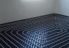
Pipe laying options: simple, angular or double loops (snakes), spirals (snails). For narrow corridors and irregularly shaped rooms, snake laying is used. Large areas are divided into sectors. Combined laying is allowed: in the edge zone, the pipe is laid out with a snake, in the main part - with a snail.

Along the perimeter, closer to the outer wall and near the window openings, the contour is fed. The laying step in the edge zones may be less than the distances between the pipes in the central part of the room. The connection of edge zone reinforcements is necessary to increase the heat flux power.
Important! Bending the pipes by 90° in a spiral scheme for connecting a water-heated floor reduces the hydraulic resistance less than when laying with loops (snake).
In the calculations of pipes for a water-heated floor, diameters of 16, 20, 26, 32 mm are used.

For systems of warm water floors, corrugated, stainless steel, copper, metal-plastic, cross-linked polyethylene pipelines are used. The corrugation of the pipe for underfloor heating has become relatively recent in order to facilitate the installation of the structure and reduce the cost of rotary increases in length.
The polypropylene pipeline has a large bending radius, so it is rarely used in underfloor heating systems.

Floor coverings
Types of finishing flooring for underfloor heating: linoleum, tile, ceramic and metlakh tiles, marble, granite, basalt and porcelain stoneware.
Wooden flooring is contraindicated in constant humidity in the room, so it is not used in bathrooms with underfloor heating.
Table 4 Thermal conductivity of floor coverings:
| Material type | Layer thickness δ, m | Density γ, kg/m³ | Thermal conductivity coefficient λ, W/(m °∁) |
| Linoleum insulated | 0,007 | 1600 | 0,29 |
| Tile, metlakh, ceramic | 0,015 | 1800 ÷ 2400 | 1,05 |
| Laminate | 0,008 | 850 | 0,1 |
| parquet board | 0.015 ÷ 0.025 | 680 | 0,15 |
| Insulation (ursa) | 0,18 | 200 | 0,041 |
| Cement-sand screed | 0,02 | 1800 | 0,76 |
| reinforced concrete slab | 0,2 | 2500 | 1,92 |

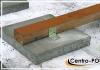
Water device in a concrete screed with a final coating of tiles
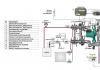
Pumping equipment in underfloor heating calculations
Reducing the temperature of the coolant allows you to achieve efficient operation of the circulation pumps.
The heating circuit of underfloor heating is located in a horizontal plane and covers a large area. The force that the circulation pump gives to the flow is spent on overcoming linear and local resistances. The calculation of the pump for underfloor heating depends on the diameter, roughness of the pipe, fittings and the length of the circuit.

The main calculation parameter is the pump performance in the low-pressure circuit:
H \u003d (P × L + ΣK) / 1000, (m), where
H - head of the circulation pump, m;
P - hydraulic loss per linear meter of length (passport data from the manufacturer), pascal / meter;
L - maximum length of pipes in the circuit, m;
K is the power reserve factor for local resistances.
K = K1 + K2 + K3, where
K1 - resistance on adapters and tees, connections (1,2);
K2 - resistance on shutoff valves (1.2);
K3 - resistance at the mixing unit in the heating system (1.3).

The degree of performance that the circulation pump has is determined by the formula:
G= Q/(1.16×∆t), (m³/h), where
1.16 - specific heat capacity of water (Wh/kgC);
∆t - heat removal in the system (for low-pressure circuits 5 ÷ 10°C).

Table 5 The dependence of the power of the unit on the area of heated premises (for hydraulic calculation of a warm floor):
| Floor area, m² | Productivity of the circulation pump for a heat-insulated floor, m³/h | |
| 80 ÷ 120 | 1,5 | |
| 120 ÷ 160 | 2,0 | |
| 160 ÷ 200 | 2,5 | |
| 200 ÷ 240 | 3,0 | |
| 240 ÷ 280 | 4,0 | |
Useful advice! The power of the unit consists of the sum of the costs of all circuits. In case of abnormal cold weather, it is necessary to provide a pump performance margin of 15 ÷ 20%.

Calculation of the cost of underfloor heating
And the floor hydraulic circuit connects the manifold. A uniform flow of the heat carrier is ensured by automatic adjustment, using balancing and thermostatic valves. The non-return valve protects the pump and mixing unit.
Table 6 Elements of a complete set of a heat-insulated floor:
| Position name | Size and unit | Price per unit of goods (rub.) |
| Waterproofing | roll (1.5×50 m) | from 2000 |
| damper tape | 25 m | from 500 |
| Shielding thermal insulation (polystyrene foam) | 1100×800×38mm | 769 |
| Pipe | 16 ÷ 20 mm | 50 ÷ 80 |
| Concrete screed: cement dry mixes | 50 kg 25 kg | 125 200 |
| Collector group assembled | 2 exits | 4600 |
| Pumping and mixing unit: thermostatic head balancing and thermostatic valves, circulation pump | set | from 20000 |
The total cost of a warm floor is determined by the area of the room, the equipment, the quality of the material and the method of work. Batch formation of a warm floor provides compatibility of elements and effective heating in the temperature ranges. Factory equipment reduces the cost of materials by 1.5-2 times.

The owner of the house can make a calculation of water heated floors, mount the system with his own hands, if he has a sufficient stock of knowledge in heat engineering, hydraulics, materials science and experience in plumbing work. The mass of positive examples from life inspires. However, everyone should carry "his own portfolio", his own house is not a springboard for experiments.